Automatic marking system

An automatic and laser marking technology, applied in the field of laser marking, can solve problems such as board indentation, uneven marking surface, and low marking efficiency

Active Publication Date: 2017-08-04
SHENZHEN SHENGDAKANG TECH CO LTD
View PDF11 Cites 10 Cited by
  • Summary
  • Abstract
  • Description
  • Claims
  • Application Information

AI Technical Summary

Problems solved by technology

For example, the loading process of PCB before marking and the unloading process after marking can only be done manually, which makes the marking efficiency low
For another example, due to the unreasonable design of the conveying, positioning and clamping equipment of the PCB board, it wil

Method used


Image

  • Automatic marking system
  • Automatic marking system
  • Automatic marking system

Examples


Embodiment

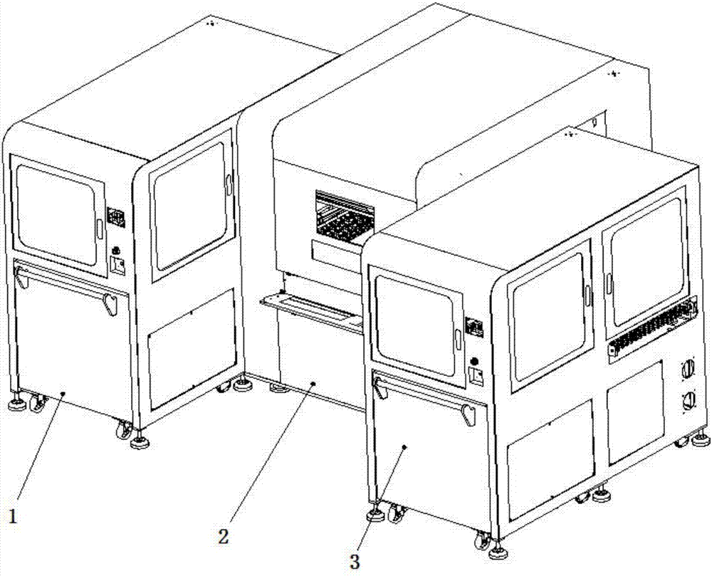
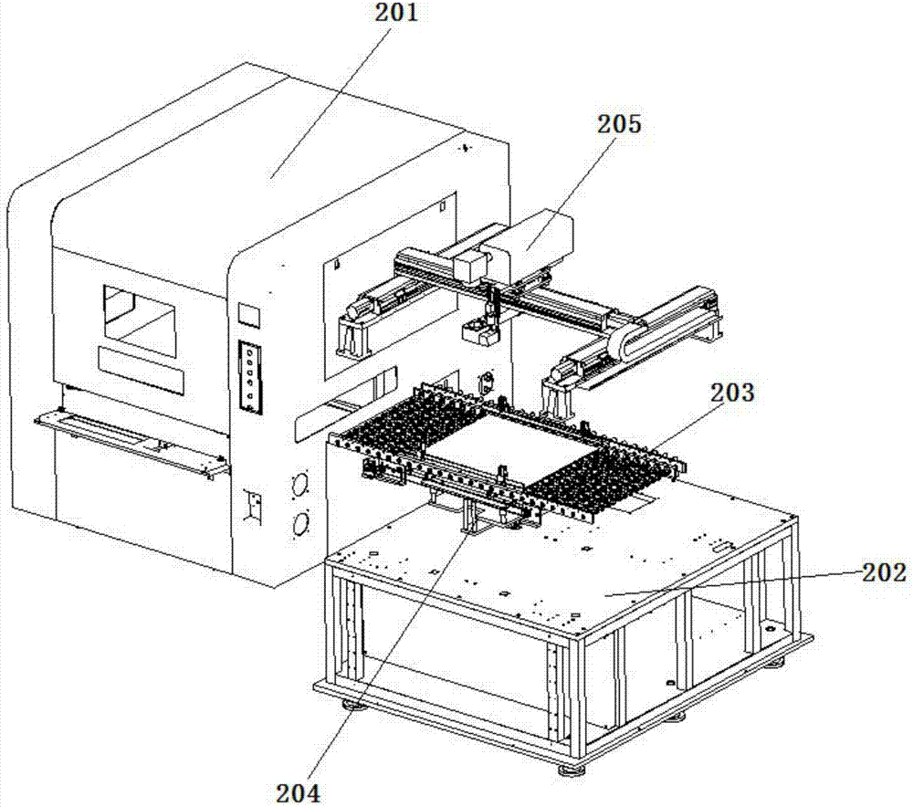
[0034] see figure 1, figure 2 , image 3 , Figure 4 , Figure 5 , an automatic marking system provided by the embodiment of the present invention, such as figure 1 , figure 2 , image 3 , Figure 4 , Figure 5 As shown, the system includes an upper board device 1, a laser marking device 2 and a lower board device 3; The board outlet of the marking device 2 is set opposite to the board inlet of the lower board device 3;

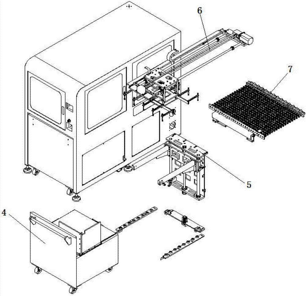
[0035] The upper board device 1 has the same structure as the lower board device 3; the upper board device 1 includes a frame for supporting and carrying various components, and a trolley assembly 4 and a lifting assembly are arranged in the frame. 5. The traversing assembly 6 and the first rail transmission assembly 7; specifically, the frame, which is used to support and carry other components; the trolley assembly 4, which is movably placed on the machine In the cavity opened by the frame, the trolley is provided with a PCB carrier plate for pl...


PUM


Abstract

The invention discloses an automatic marking system which comprises a plate feeding device, a laser marking device and a plate discharging device, wherein a plate outlet of the plate feeding device corresponds to a plate inlet of the laser marking device; and a plate outlet of the laser marking device is opposite to a plate inlet of the plate discharging device. According to the system provided by the invention, the plate feeding device and the plate discharging device can realize automatic plate feeding and discharging; and all the components of the system are closely connected, and different working procedures are cooperated smoothly. A portal assembly in the laser marking device is of a dual-Y-shaft and X-shaft cooperation driving structure, and the double Y shafts can solve the problems of asynchronization of the two Y shafts, heavy shaking and the like in case of a large cross beam span. The marking speed and the precision are improved to a relatively large extent; and the height of a laser device can be finely adjusted (within a range of positive and negative 15 mm) through a screw rod, so that the automatic marking system can adapt to marking procedures of various PCBs with different thicknesses.

Description

technical field [0001] The invention relates to the technical field of laser marking, in particular to a laser automatic marking system capable of automatically loading and unloading plates. Background technique [0002] Laser marking is a method of leaving a permanent mark on the surface of a material by using the high peak power density of a focused laser beam to evaporate or photophysically and chemically change the material surface. PCB laser marking machine is a special model specially used for marking barcode, two-dimensional code, characters, graphics and other information on printed circuit boards. It integrates a high-performance CO2 / Fiber light source and a high-pixel imported CCD camera, and cooperates with a micron-level mobile module to realize automatic positioning before coding and automatic code reading and rating after coding. [0003] The laser marking equipment in the prior art has many defects due to the lack of relevant supporting equipment. For exampl...

Claims


Application Information

Patent Timeline
IPC IPC(8): B23K26/362B23K26/352B23K26/08B23K26/70
CPCB23K26/0869B23K26/352B23K26/361B23K26/702
Inventor 韩飞李丙生梁发新张杰
Owner SHENZHEN SHENGDAKANG TECH CO LTD
Why Eureka
Try Eureka