Grinding equipment for cathode roller

A cathode roller and equipment technology, which is applied in the direction of grinding/polishing equipment, metal processing equipment, grinding machines, etc., can solve the problems of slow grinding platform speed, excessive grinding wheel grinding, and damage to the surface of the cathode roller, so as to ensure the grinding quality , Guaranteed grinding effect, avoiding excessive wear

Active Publication Date: 2017-08-04
GUANGDONG FINE YUAN SCI TECH CO LTD
View PDF8 Cites 21 Cited by
  • Summary
  • Abstract
  • Description
  • Claims
  • Application Information

AI Technical Summary

Problems solved by technology

[0003] However, in the actual grinding process, manual observation and manual control of the grinding machine are still required to grind the cathode roll
In actual production, the applicant found that: due to the slow speed of the grinding platform, as used for the production of cathode rollers for very low-profile copper foil, the speed is only 4.2-5.5cm/min (0.7-0.92mm/s), At such low speeds, it is difficult for a human to identify when the grinding table has stopped moving
Since the Ra of the cathode roller is very low, once the grinding platform stops moving due to various reasons (such as circuit failure, mechanical failure light), it will cause the circumferential direction of the grinding wheel to the cathode roller (the cathode roller keeps rotating) or the contact point (cathode roller When the rotation is stopped), excessive grinding will cause fatal damage to the roll surface of the cathode roll
In the same way, if the cathode r

Method used


Image

  • Grinding equipment for cathode roller
  • Grinding equipment for cathode roller
  • Grinding equipment for cathode roller

Examples


Embodiment Construction

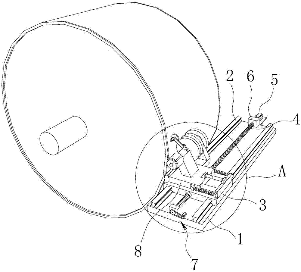
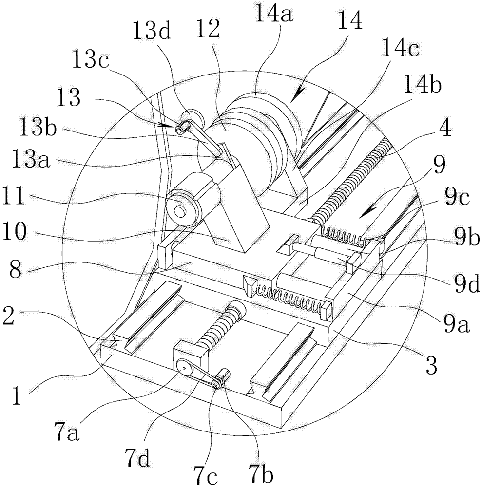
[0020] refer to Figure 1 to Figure 4 As shown, a cathode roller grinding device of the present invention includes a support 1 arranged on the side of the cathode roller surface. In this embodiment, the rotation speed of the cathode roller is 13-15 rpm. The support 1 is provided with a guide rail 2, the guide rail 2 is parallel to the axis of the cathode roller, the guide rail 2 is provided with an axial sliding seat 3, and the axial sliding seat 3 is threadedly connected with a driving screw 4, and the driving screw 4 The first driving motor 5 is connected, the driving screw 4 is arranged parallel to the guide rail 2 , and the two ends of the support 1 along the length direction are respectively provided with supporting seats 6 matched with the driving screw 4 . With this structure, the axial sliding seat 3 reciprocates along the cathode roller axis under the cooperation of the driving screw 4 , the first driving motor 5 and the supporting seat 6 . In the present embodiment,...


PUM


Abstract

The invention discloses grinding equipment for a cathode roller and belongs to the technical field of grinding equipment. According to the technical key point, the grinding equipment comprises a support arranged on the side edge of the roller surface of the cathode roller; guide rails are arranged on the support; an axial sliding seat is arranged on the guide rails and connected with a driving screw rod in a threaded mode; the driving screw rod is connected with a first driving motor, and the driving screw rod and the guide rails are arranged parallelly; supporting seats matched with the driving screw rod are arranged at the two ends in the length direction of the support correspondingly; the driving screw rod is connected with a displacement detecting mechanism; a radial sliding seat is movably arranged on the axial sliding seat and connected with a radial driving mechanism; an installing table is arranged on the radial sliding seat; a second driving motor is installed on the installing table in the axial direction of the cathode roller; and a power output shaft of the second driving motor is connected with a grinding wheel. The grinding equipment for the cathode roller is reasonable in structure, high in using safety, convenient to use and used for grinding the cathode roller.

Description

technical field [0001] The present invention relates to an auxiliary equipment for copper foil production, more specifically, it relates to a grinding equipment for cathode rollers. Background technique [0002] In the raw foil process of electrolytic copper foil, when the cathode roller is used for a certain period of time or when there is an abnormality on the roller surface, the cathode roller needs to be hoisted to a specific roller room for grinding. The grinding needs to be repeated several times, and the duration is several hours or even days. [0003] However, in the actual grinding process, manual observation and manual control of the grinding machine are still required to grind the cathode roll. In actual production, the applicant found that: due to the slow speed of the grinding platform, as used for the production of cathode rollers for very low-profile copper foil, the speed is only 4.2-5.5cm / min (0.7-0.92mm / s), At such low speeds, it is difficult for a human ...

Claims


Application Information

Patent Timeline
IPC IPC(8): B24B5/37B24B49/02B24B41/02
CPCB24B5/37B24B41/02B24B49/02
Inventor 庄如珍王崇华王俊锋陈优昌廖平元李建国刘少华张小玲黄勇叶敬敏
Owner GUANGDONG FINE YUAN SCI TECH CO LTD
Why Eureka
Try Eureka