A hydraulic rotary shoe guide

A hydraulic rotation and shoe-guiding technology, which is applied in the direction of drill pipe, casing, wellbore/well parts, etc., can solve the problems of high casing friction resistance, affecting casing running speed, and single function, so as to reduce friction The effect of resisting and improving chip carrying ability

Inactive Publication Date: 2019-03-05
SOUTHWEST PETROLEUM UNIV
View PDF1 Cites 0 Cited by
  • Summary
  • Abstract
  • Description
  • Claims
  • Application Information

AI Technical Summary

Problems solved by technology

[0002] The role of the traditional guide shoe in casing running is very simple, because the traditional guide shoe is fixed, and the outer diameter of the guide shoe is the same as the outer diameter of the casing, and the casing running friction is very large, which cannot solve the problem of wellbore shrinkage. Due to the diameter problem, the cuttings-carrying ability of the drilling fluid cannot be improved, the casing running speed is affected, and even stuck, which makes it impossible to run the casing smoothly into the well and affects the cementing quality
Chinese invention patent "A Rotary Guide Shoe" (201310568676.6) Due to the small power provided by the drilling fluid flowing through the turbine blades, it is impossible to form a turbulent flow of the drilling fluid downhole to improve the cuttings carrying capacity of the drilling fluid; the bottom end of the rotating seat is Conical, with a large bottom and a small upper end, combined with low power, it is easy to insert into the ground when it encounters a long horizontal section or when the ground collapses, causing it to get stuck

Method used


Image

  • A hydraulic rotary shoe guide
  • A hydraulic rotary shoe guide
  • A hydraulic rotary shoe guide

Examples


Embodiment Construction

[0022] The present invention will be described in further detail below in conjunction with the accompanying drawings.

[0023] see figure 1 , figure 2 , image 3 , Figure 4 .

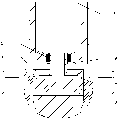
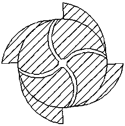
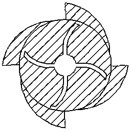
[0024] A hydraulic rotary guide shoe is composed of a casing joint, a rotating body and a tapered bearing 1. The casing joint is a hollow cylindrical barrel with an outer diameter slightly larger than the outer diameter of the casing. There is a drilling fluid channel in the lower part, an internal thread 4 at the top, and a reinforcing point 5 at the bottom; the casing joint and the rotating body Connected by a conical bearing 1, the conical bearing is embedded in the bottom of the cylindrical barrel through a sealing ring 6; the rotating body is a hemispherical body with a diameter slightly larger than the outer diameter of the casing, and the drilling fluid channel on the upper part is connected to the drilling fluid channel on the lower part of the casing joint Connected, with a spiral blade ...


PUM


Abstract

The invention discloses a hydraulic rotary guiding shoe. The hydraulic rotary guiding shoe is composed of a casing pipe connector, a rotating body and a conical bearing 1. The casing pipe connector is of a hollow cylindrical barrel structure, the outer diameter of the casing pipe connector is a little larger than that of a casing pipe, a drilling fluid channel is formed in the lower portion of the casing pipe connector, the top end of the casing pipe connector is provided with an inner thread 4, and the bottom end of the casing pipe connector is provided with reinforcement points 5; the casing pipe connector is connected with the rotating body through the conical bearing 1, and the conical bearing is embedded in the bottom of the cylindrical barrel through a sealing ring 6; the rotating body is in a hemispheroid shape, the diameter of the rotating body is a little larger than the outer diameter of the casing pipe, a drilling fluid channel in the upper portion of the rotating body is communicated with the drilling fluid channel in the lower portion of the casing pipe connector, helical blades 2 are arranged on the upper end surface of the rotating body, scrapers 3 in an arc-conical shape are arranged on the side surface of the rotating body, two layers of turbine flowing channels are formed in the hemispheroid, draining holes of the first-layer turbine flowing channel 7 face towards a casing pipe column, and draining holes of the second-layer turbine flowing channel 8 are formed in a concave portion between adjacent scrapers. The hydraulic rotary guiding shoe is reliable in principle, simple in structure and low in cost; not only can friction drag of casing pipe running be reduced, but the hydraulic rotary guiding shoe has the function of reaming, and the hydraulic rotary guiding shoe has broad market prospects.

Description

technical field [0001] The invention relates to a hydraulic rotary guide shoe used in the well cementing process in the field of petroleum and natural gas development. Background technique [0002] The role of the traditional guide shoe in casing running is very simple, because the traditional guide shoe is fixed, and the outer diameter of the guide shoe is the same as the outer diameter of the casing, and the casing running friction is very large, which cannot solve the problem of wellbore shrinkage. Due to the diameter problem, the cuttings-carrying ability of the drilling fluid cannot be improved, the casing running speed is affected, and even stuck, which makes it impossible to smoothly run the casing into the well and affects the cementing quality. Chinese invention patent "A Rotary Guide Shoe" (201310568676.6) Due to the small power provided by the drilling fluid flowing through the turbine blades, it is impossible to form a turbulent flow of the drilling fluid downhol...

Claims


Application Information

Patent Timeline
Patent Type & Authority Patents(China)
IPC IPC(8): E21B17/14E21B21/00E21B29/00
CPCE21B17/14E21B21/00E21B29/00
Inventor 徐璧华张彪唐巍谢应权王俊杰谭元铭
Owner SOUTHWEST PETROLEUM UNIV
Why Eureka
Try Eureka