
Self-lubricating heavy-load support sliding sleeve

A self-lubricating and sliding sleeve technology, which is applied in the direction of engine lubrication, bearings, shafts and bearings, etc., can solve the problems of lack of self-lubricating effect, difficult formation of lubricating film, stress damage, etc., and achieve weight reduction and deformation stress Uniform, uniform stress effect

Active Publication Date: 2017-08-04
WISDRI ENG & RES INC LTD
View PDF8 Cites 1 Cited by
  • Summary
  • Abstract
  • Description
  • Claims
  • Application Information

AI Technical Summary

Problems solved by technology

[0002] In heavy industry, especially mining, metallurgy and other industries, mechanical equipment often bears heavy loads of tens of tons or even hundreds of tons. Heavy loads will cause greater stress and damage to key components such as shafts and bearings of mechanical equipment, so It is necessary to put a supporting sliding sleeve on the key parts to reduce the stress. The existing supporting sliding sleeve is generally a thin-walled annular cylinder structure, and a self-lubricating body is embedded on the cylinder wall to realize the self-lubricating function. The existing self-lubricating The bearing sliding sleeve has the following problems: 1) The self-lubricating bearing sliding sleeve deforms very little under the limitation of wall thickness, and will directly transmit the heavy load to the key components; 2) The self-lubricating body is generally grease, when the pressure per unit area is too high It is not easy to form a lubricating film and cannot achieve self-lubricating effect

Method used


Image

  • Self-lubricating heavy-load support sliding sleeve
  • Self-lubricating heavy-load support sliding sleeve

Examples


Embodiment Construction

[0023] The present invention will be further described below in conjunction with the accompanying drawings and embodiments.

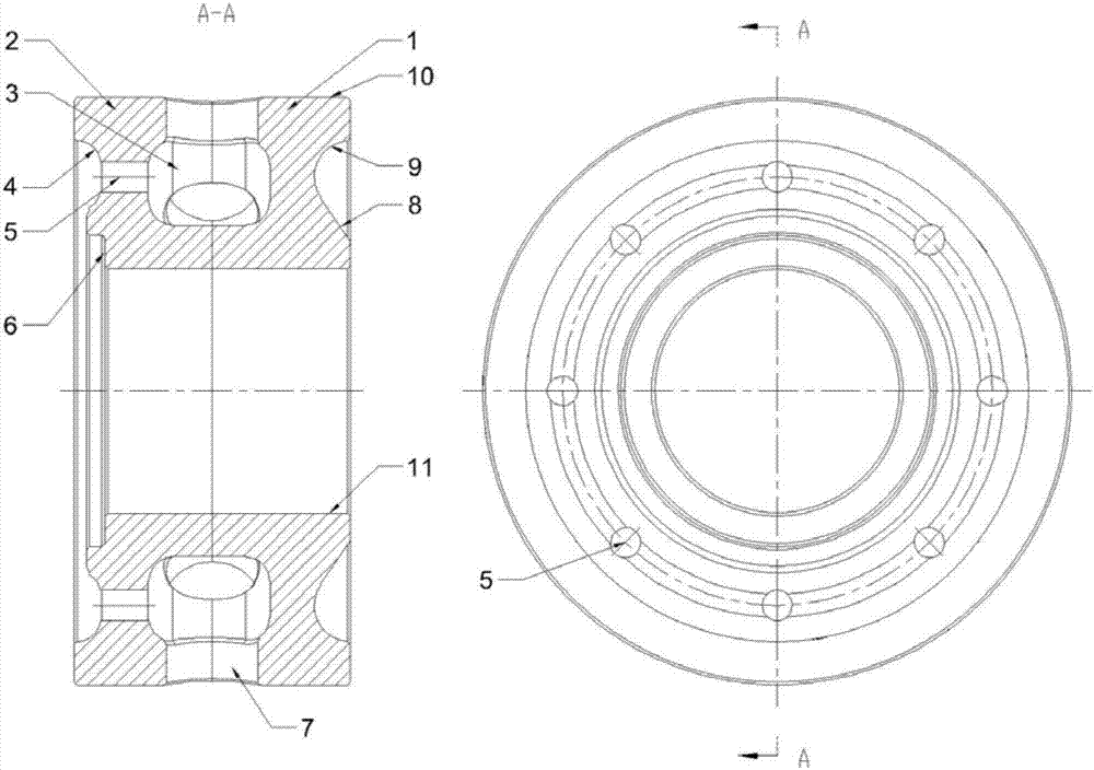
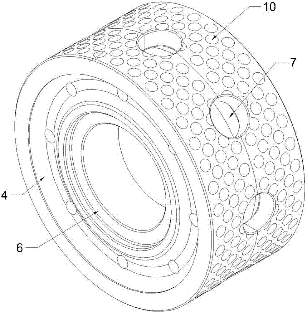
[0024] Such as figure 1 and figure 2 As shown, a self-lubricating heavy-duty bearing sliding sleeve includes a thick-walled cylinder with a shaft hole 11, a self-lubricating body is provided on the outer wall of the cylinder, and first stress unloading holes 7 are evenly distributed along the circumferential direction in the middle. The side of the first stress unloading hole 7 pointing to the axis of the cylinder is connected with a stress unloading cavity 3, the stress unloading cavity 3 is wider than the first stress unloading hole 7 and is symmetrical about the axis of the first stress unloading hole 7, the cylinder body A shaft cover fixing groove 6 is provided on the end face. The bearing sliding sleeve cooperates with the shaft end cover to lock the shaft end through the shaft end cover fixing groove 6 (the shaft end cover fixing groove 6 is u...


PUM


Abstract

The invention relates to a self-lubricating heavy-load support sliding sleeve comprising a thick-wall barrel with an axle hole; the outer wall of the barrel is provided with a self-lubricating body, and first stress unloading holes are evenly distributed in the middle of the barrel circumferentially; the sides, pointing to the axis of the barrel, of the first stress unloading holes all communicate with stress unloading cavities wider than the first stress unloading holes and symmetrical relative to the axis of the first stress unloading holes; and one end face of the barrel is provided with a shaft end cover fixing groove. In the support sliding sleeve, materials of non-bearing areas are reduced properly, and part load is evenly absorbed through reasonable self-deformation, so that the purpose of reducing the weight of the whole support sliding sleeve is achieved, and the design difficulty of other components in combined use is reduced.

Description

technical field [0001] The invention relates to a supporting sliding sleeve, in particular to a self-lubricating heavy-duty supporting sliding sleeve. Background technique [0002] In heavy industry, especially mining, metallurgy and other industries, mechanical equipment often bears heavy loads of tens of tons or even hundreds of tons. Heavy loads will cause greater stress and damage to key components such as shafts and bearings of mechanical equipment, so It is necessary to put a supporting sliding sleeve on the key parts to reduce the stress. The existing supporting sliding sleeve is generally a thin-walled annular cylinder structure, and a self-lubricating body is embedded on the cylinder wall to realize the self-lubricating function. The existing self-lubricating The bearing sliding sleeve has the following problems: 1) The self-lubricating bearing sliding sleeve deforms very little under the limitation of wall thickness, and will directly transmit the heavy load to the...

Claims


Application Information

Patent Timeline
Patent Type & Authority Applications(China)
IPC IPC(8): F16C33/04F16C33/10F16C39/02F16N15/02
CPCF16C33/04F16C33/1095F16C39/02F16C2202/52F16C2361/31F16C2352/00
Inventor 褚学征张文张愉
Owner WISDRI ENG & RES INC LTD
Learn More