
Method for optimizing dynamic property of optical fiber gyro

A dynamic performance, fiber optic gyroscope technology, applied in Sagnac effect gyroscopes and other directions, can solve the problem that the process cannot be reflected and cannot explain the zero bias effect of the gyro gyroscope, achieve accurate prediction of dynamic performance, and improve dynamic performance. Effect

Active Publication Date: 2017-08-04
TIANJIN NAVIGATION INSTR RES INST
View PDF4 Cites 10 Cited by
  • Summary
  • Abstract
  • Description
  • Claims
  • Application Information

AI Technical Summary

Problems solved by technology

In the simplified closed-loop model of the fiber optic gyroscope, since the demodulation module is simplified into a link with a fixed gain, this process cannot be reflected
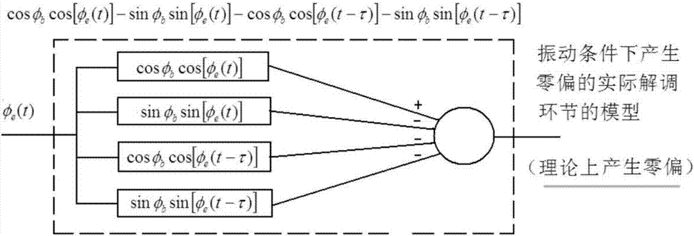
The traditional simplified model cannot explain the gyroscope zero bias effect during the vibration process of the gyroscope

Method used


Image

  • Method for optimizing dynamic property of optical fiber gyro
  • Method for optimizing dynamic property of optical fiber gyro
  • Method for optimizing dynamic property of optical fiber gyro

Examples


Embodiment Construction

[0031] Embodiments of the present invention are described in further detail below in conjunction with the accompanying drawings:

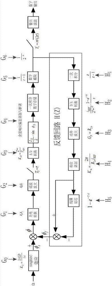
[0032] A method to optimize the dynamic performance of fiber optic gyro, such as figure 1 shown, including the following steps:

[0033] Step 1. Establish a simplified closed-loop model of the gyroscope.

[0034] figure 1 The mathematical expressions of each link of the closed-loop model are given. The forward channel is represented by G, and each link is represented by G 0 , G 1 ...... G 6 Indicates that the backward channel is represented by H, and each link is H 1 、H 2 ......H 5 . Among them, the various links of the forward channel are: sagnac effect (G 0 ), photoelectric conversion (G 1 ), filter amplification (G 2 ), AD conversion (G 3 ), cosine response bias modulation and demodulation (G 4 ), one-time integral digital storage (G 5 ) and digital truncation (G 6 ); each link of the backward channel is as follows: quadratic int...


PUM


Abstract

The invention relates to a method for optimizing the dynamic property of an optical fiber gyro, which comprises sequentially connected forward path links: sagnac effect, photoelectric conversion, filtering amplification, AD conversion, cosine response bias modulation and demodulation, first field integral digital storage and digital interception, and sequentially connected backward links: second order integral, D / A conversion power amplification, power amplification, phase modulation and coil delaying. The treatment procedure comprises the following steps: establishing a simplified gyro closed-loop model; establishing a precise gyro closed-loop model; determining gyro stabilization and over modulation conditions; and selecting closed-loop parameters for the optical fibre gyro, and predicting gyro dynamic property through simulation. The method of the invention is reasonable in design, can realize zero bias effect prediction of the gyro during vibration, provides reference for optimizing gyro closed-loop parameters, and improves the dynamic property of the optical fiber gyro.

Description

technical field [0001] The invention belongs to the technical field of optical fiber gyroscopes, in particular to a method for optimizing the dynamic performance of optical fiber gyroscopes. Background technique [0002] Fiber optic gyroscope is a new type of all-solid-state inertial instrument, which has the advantages of low cost, long life, large dynamic range and high reliability, and has been widely used in military and civilian fields. When the FOG's zero bias (mean value) is slightly shifted during the vibration process (whether it is random or frequency sweep), the accuracy of the FOG is seriously reduced. The reason is that the feedback signal always lags behind the Sagnac phase because of the delay, overshoot, etc. in the fiber optic gyro loop. When the angular rate changes due to acceleration or deceleration, the feedback phase always tries to keep up with the actual feedback phase, and there is a transient residual error signal. This residual error signal becom...

Claims


Application Information

Patent Timeline
IPC IPC(8): G01C19/72
CPCG01C19/72
Inventor 张书颖张贵材马林陈馨林毅左文龙高洪宇
Owner TIANJIN NAVIGATION INSTR RES INST
Learn More