Experimental system for analyzing dynamic scaling trend of geothermal water

A technology of trend analysis and experimental system, applied in the direction of testing water, material inspection products, etc., can solve the problems of high experimental cost and poor system applicability, and achieve the effect of convenient experimental research, low cost and simple structure

Pending Publication Date: 2017-08-04
QINGDAO UNIV OF SCI & TECH
View PDF0 Cites 6 Cited by
  • Summary
  • Abstract
  • Description
  • Claims
  • Application Information

AI Technical Summary

Problems solved by technology

[0004] In order to study the fouling process of geothermal water under different working conditions and break through the problems of high experimental cost and poor system applicability in the past, the present invention provides a small space occupation, simple structure, convenient operation, low cost, real-time detection, and safety factor High, an experimental system that can effectively analyze the dynamic scaling trend of various geothermal waters

Method used


Image

  • Experimental system for analyzing dynamic scaling trend of geothermal water
  • Experimental system for analyzing dynamic scaling trend of geothermal water
  • Experimental system for analyzing dynamic scaling trend of geothermal water

Examples


Embodiment approach

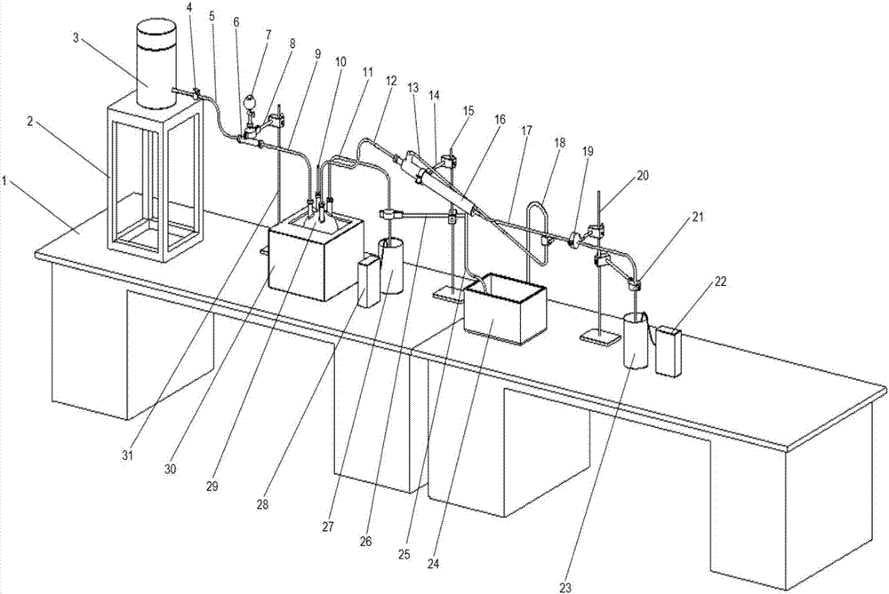
[0019] refer to Figure 1 to Figure 3 , The present invention is an experimental system for dynamic scaling trend analysis of geothermal water, which is composed of an auxiliary system, a visualization system, a detection system, a storage system and a heating system.

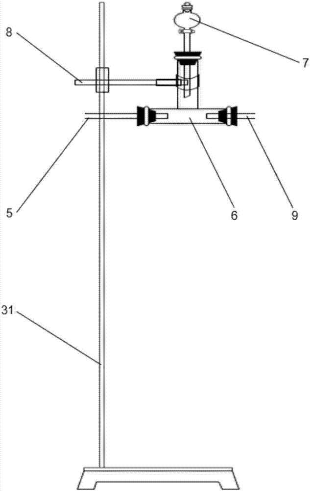
[0020] The auxiliary system consists of test bench (1), bracket (2), iron stand I (15), iron stand II (20), iron stand III (31), flask clamp I (8), flask clamp II (14), flask Clamp III (19), flask clamp IV (21), flask clamp V (26) and condensate pipe (18), the bracket (2) is used to support the water storage bucket (3), and the iron stand III (31) is used to fix the three Pass (6), iron stand I (15) is used to fix the condensation pipe (16) and conduit III (11), iron stand II (20) is used to fix the conduit VI (17), each part is built on the test bench (1) above, constitute the whole experimental system.

[0021] The visualization system consists of valve (4), conduit I (5), conduit II (9), conduit III (11), ...

Embodiment

[0027] like Figure 1 to Figure 3 As shown, the bracket (2) is placed on the test bench (1), the water storage bucket (3) is placed on the bracket (2), and the water storage bucket (3) and the tee (6) are connected through the conduit I (5). Use the iron stand III (31) and the flask clamp I (8) to fix the tee (6), place the dropping funnel (7) on the tee (6), and use the dropping funnel (7) to drop various additives; Connect the tee (6) to a bottle mouth on the four-necked flask (29) through the conduit II (9), and the thermometer (10) is placed in a bottle mouth on the four-necked flask (29), and use the conduit IV ( 12) Lead sampled water from a bottle mouth on the four-neck flask (29) to the beaker II (27), use the scale ion detector II (28) to measure the concentration of scale ions in the water, and use the iron stand I (15 ) and flask clamp V (26) to fix the conduit III (11), and the four-necked flask (29) utilizes a magnetic stirring electric heater (30) to heat; conn...


PUM


Abstract

The invention relates to an experimental system for analyzing the dynamic scaling trend of geothermal water, which is beneficial to the research on the scaling problem of geothermal water and the optimization of scale inhibitors. The invention belongs to the technical field of geothermal exploitation. The device consists of auxiliary system, visualization system, detection system, storage system and heating system. Several simple experimental components can be combined into a complete experimental system after appropriate adjustments. According to the specific requirements of the experiment, different types of experimental components can be selected. Each experimental component is visualized and can be intuitively observed. The dynamic formation process of scale can be studied at the same time, and the scale inhibition effect after adding scale inhibitor can be studied. The experimental device has the advantages of small space occupation, simple structure, convenient operation, low cost and real-time detection, which is beneficial to the research on the problem of scaling and scale inhibition of geothermal water.

Description

technical field [0001] The invention relates to an experimental system for analyzing the dynamic scaling trend of geothermal water. Through a visualized experimental device, the scaling process of geothermal water can be observed in real time, and belongs to the technical field of geothermal exploitation. Background technique [0002] With the promotion and application of geothermal resources in my country, water scaling has become one of the key factors restricting its effective development and recycling. How to effectively analyze the dynamic scaling trend and law of geothermal water, and quickly screen out high-efficiency scale inhibitors has become one of the hot spots of current experimental research. [0003] Most of the existing geothermal water scaling analysis experimental systems only conduct experimental research on a certain problem and factor, and cannot intuitively analyze the scaling trend under different working conditions. Moreover, the cost of the entire se...

Claims


Application Information

Patent Timeline
Patent Type & Authority Applications(China)
IPC IPC(8): G01N33/18
CPCG01N33/18
Inventor 巢昆郑尚基张国栋王枫杜东兴翟佩斯利
Owner QINGDAO UNIV OF SCI & TECH
Why Eureka
Try Eureka