
Electrical connector

A technology of electrical connectors and welding parts, which is applied in the direction of conductive connection, connection, and two-component connection devices, and can solve problems such as high impedance and affecting signal transmission efficiency

Active Publication Date: 2017-08-04
MOLEX INC
View PDF9 Cites 3 Cited by
  • Summary
  • Abstract
  • Description
  • Claims
  • Application Information

AI Technical Summary

Problems solved by technology

[0002] Generally, there are electrical connectors with welded wires, such as disclosed in Taiwan Patent No. 575256. The place where the wires and the terminals of the electrical connector are welded is exposed to the air, and the dielectric coefficient of the air is smaller than that of the insulating body. , so a higher impedance will be generated here and affect the performance of signal transmission

Method used


Image

  • Electrical connector
  • Electrical connector
  • Electrical connector

Examples


Embodiment Construction

[0051] Before the present invention is described in detail, it should be noted that in the following description, similar elements are denoted by the same numerals.

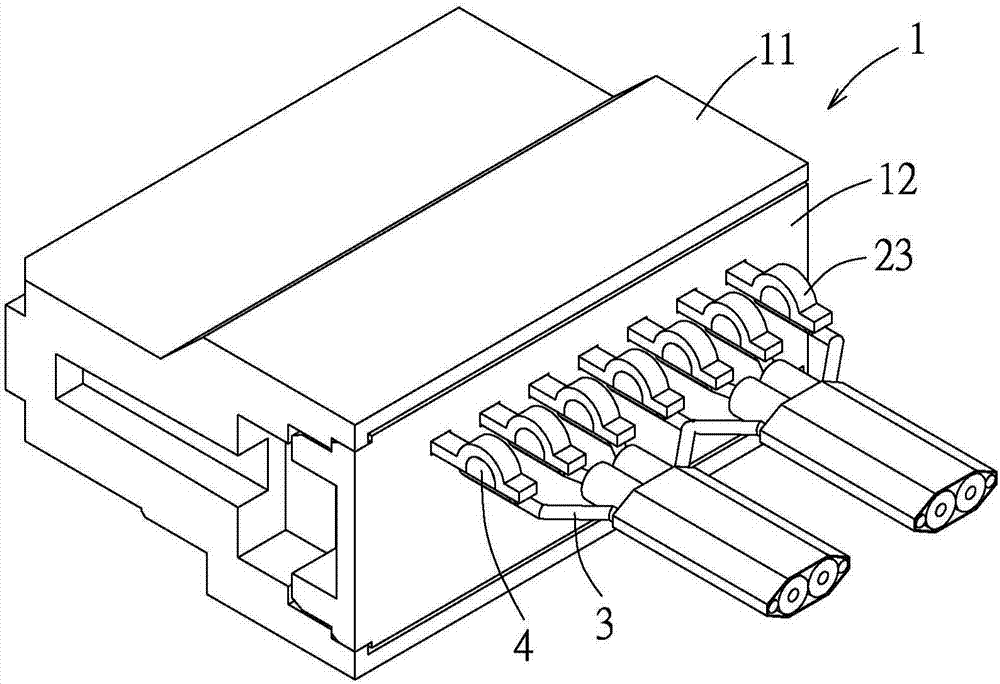
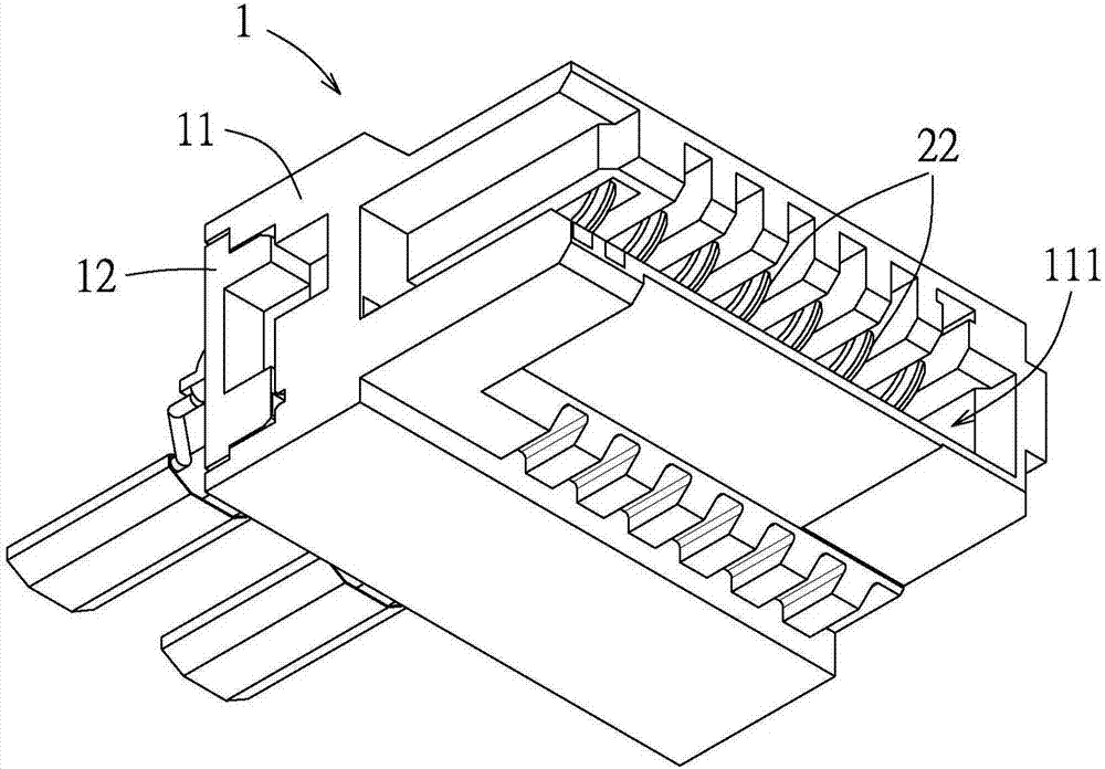
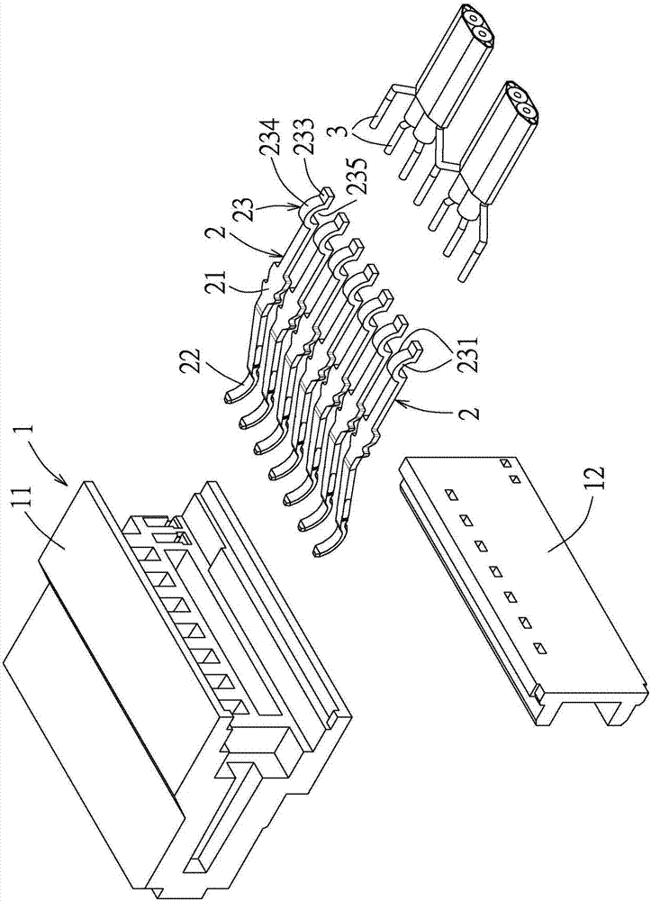
[0052] refer to Figure 1 to Figure 4 , a first embodiment of the electrical connector of the present invention includes an insulating shell 1 , a plurality of terminals 2 and a plurality of wires 3 . In this embodiment, the insulating case 1 includes a main body 11 and a back cover 12 combined with the main body 11 , but the insulating case 1 may also only include the main body 11 , that is, the back cover 12 is omitted. The body 11 has a slot 111 .

[0053] A plurality of terminals 2 are fixed on the insulating case 1 side by side. Each terminal 2 has a fixing portion 21 fixed to the insulating shell 1 , a contact portion 22 and a soldering portion 23 connected to the fixing portion 21 . The contact portion 22 extends into the slot 111 . The welding portion 23 protrudes from the back cover 12 and has a firs...


PUM


Abstract

An electrical connector comprises an insulation shell, a plurality of terminals and a plurality of wires, wherein the plurality of terminals are fixedly arranged on the insulation shell, each terminal is provided with a fixed part, a contact part and a welding part, the fixed part is fixed on the insulation shell, the contact part and the welding part are connected with the fixed part, a bending segment is individually formed at the welding parts of at least one part of terminals in the plurality of terminals, a filling space is defined in an inner surface of the bending segment and is used for filling soldering flux, the plurality of wires are respectively welded with the welding parts of the plurality of terminals, and each filling space is filled with the soldering flux.

Description

technical field [0001] The invention relates to an electric connector, in particular to an electric connector with welding wires. Background technique [0002] Generally, there are electrical connectors with welded wires, such as disclosed in Taiwan Patent No. 575256. The place where the wires are welded to the terminals of the electrical connector is exposed to the air, and the dielectric coefficient of the air is smaller than that of the insulating body. , so a higher impedance will be generated there, which will affect the performance of signal transmission. Contents of the invention [0003] Therefore, one object of the present invention is to provide an electrical connector that can reduce the impedance of the welding area between the wire and the terminal. [0004] Therefore, in some embodiments, the electrical connector of the present invention includes an insulating shell, a plurality of terminals and a plurality of wires. The plurality of terminals are fixed on ...

Claims


Application Information

Patent Timeline
IPC IPC(8): H01R13/02H01R13/648H01R4/02
CPCH01R4/023H01R13/02H01R13/648H01R13/41H01R13/6471H01R13/6474H01R2107/00H01R13/405H01R24/62
Inventor 江岳庭曾珽章
Owner MOLEX INC
Learn More