Engraving machine

A technology of engraving machine and frame, which is applied in the field of engraving machines, can solve the problems of reduced precision and achieve the effect of improving precision and strengthening structural strength

Active Publication Date: 2017-08-08
玉环圣弘法数控雕刻设备有限公司
View PDF7 Cites 2 Cited by
  • Summary
  • Abstract
  • Description
  • Claims
  • Application Information

AI Technical Summary

Problems solved by technology

[0004] The purpose of the present invention is to solve the above problems in the existing technology, and propose an engraving machine, which can solve the problem of reduced precision during use and prolong the service life

Method used


Image

  • Engraving machine
  • Engraving machine
  • Engraving machine

Examples


Embodiment 1

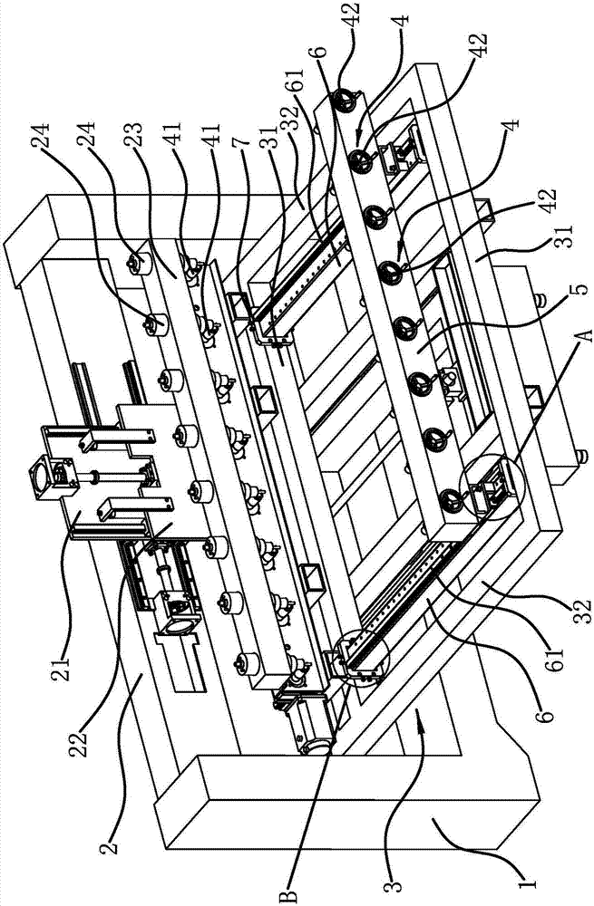
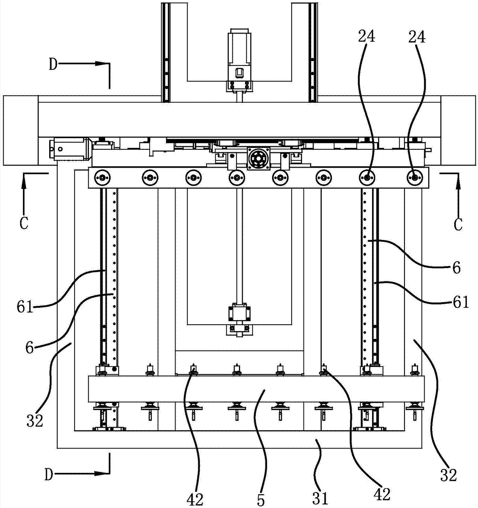
[0034] like figure 1 As shown, a kind of engraving machine comprises frame 1, and the width direction of frame 1 is transverse, is fixedly connected with crossbeam 2 on frame 1, and this crossbeam 2 is arranged along the width direction of frame 1, on crossbeam 2 along the transverse direction Slidingly connected with a horizontal supporting plate 21, the horizontal supporting plate 21 is vertically slidably connected with a vertical supporting plate 22, and the vertical supporting plate 22 is fixedly connected with a tool holder 23. A plurality of downward carving cutter heads 24 are connected along the length direction. to combine figure 2 As shown, the frame 1 is also slidably connected with a working platform 3, the working platform 3 is located below the tool holder 23, and the working platform 3 can move along the front and rear directions of the frame 1, and the working platform 3 becomes a rectangular frame shape. 3 is provided with two supporting beams 6 and a posi...

Embodiment 2

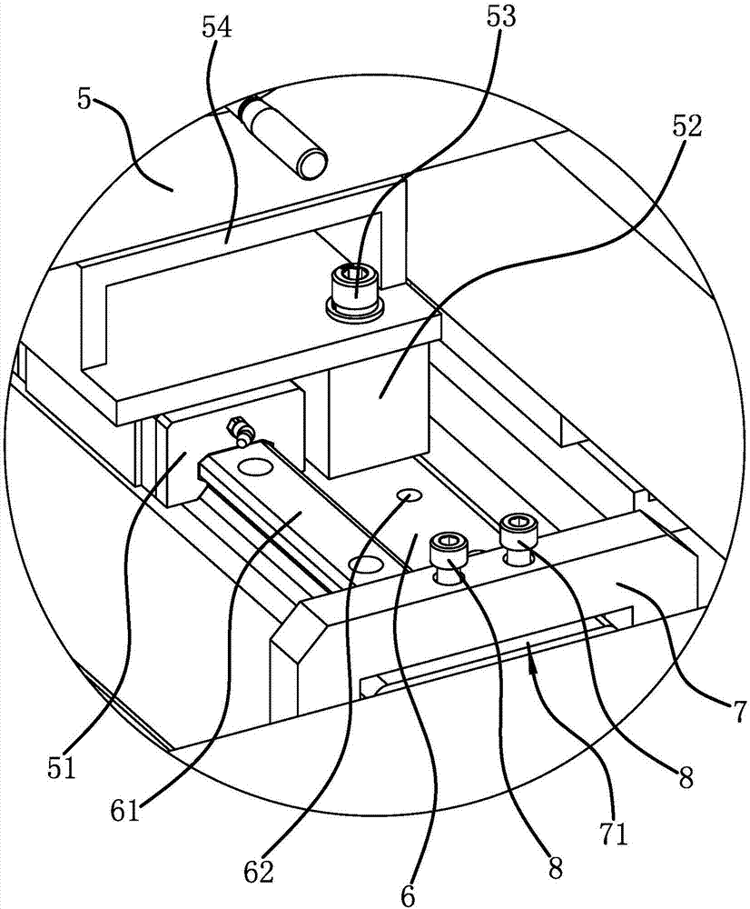
[0037] The structure of the engraving machine is basically the same as that of Embodiment 1, the difference is that Figure 9 As shown, the support body 7 includes four support blocks 73, and the four support blocks 73 are all fixed on the inner side of the working platform 3 by screws, wherein two support blocks 73 are distributed along the lateral direction, and the other two support blocks 73 are vertically distributed. Distributed, the area in the middle of the four support blocks 73 forms the socket 71, and each support block 73 is screwed with two fixing bolts 8.

Embodiment 3

[0039] The structure of the engraving machine is basically the same as that of Embodiment 1, the difference is that Figure 10 As shown, the support beam is made into a cylindrical guide rail 10, and a rectangular block-shaped connection seat 9 is fixed at the end of the cylindrical guide rail 10. The connection seat 9 is inserted into the support body 7, and the fixing bolt 8 is locked against the On the outer surface of the connecting seat 9, when the cylindrical guide rail 10 of this structure is adopted, the positioning beam 5 is slidably connected on the cylindrical guide rail 10 through the guide sleeve, that is, the lower side of the positioning beam 5 two ends is fixed with an adjustment spacer 54, and when adjusting The lower side of the cushion block 54 is fixedly connected with a guide sleeve, and the guide sleeve is slidably sleeved on the cylindrical guide rail 10 .


PUM


Abstract

The invention provides an engraving machine, and belongs to the technical field of machinery. The engraving machine solves the problem that the accuracy of the existing engraving machine is reduced in the use process. The engraving machine comprises a rack and a cross beam; a horizontal backing plate, a vertical backing plate and a tool frame are connected on the cross beam; a working platform is further connected on the rack; two support beams are further arranged on the working platform; the two ends of a locating beam are respectively connected with the two support beams in a sliding manner; insertion openings formed by a support body are arranged at the front part and the back part of the working platform; two ends of the support beam are respectively connected in the insertion openings in an inserted manner; a gap is formed between the support beam and the inner side surface of the insertion opening; at least four fixing pieces are connected on the support body, wherein at least two fixing pieces are respectively located on the horizontal two sides of the support beam and horizontally lock and fix the support beam, and at least two fixing pieces are respectively located on the upper side and the lower side of the support beam and vertically lock and fix the support beam. The locating beam of the engraving machine moves more stably and more smoothly.

Description

technical field [0001] The invention belongs to the technical field of machinery and relates to an engraving machine. Background technique [0002] From the processing principle, engraving is a combination of drilling and milling. It has a wide range of applications, including woodworking engraving machines, laser engraving machines, advertising engraving machines, jade engraving machines, stone engraving machines, cylindrical engraving machines, etc. The engraving machine has a wide range of applications, and even replaces manual engraving technology, laying the foundation for mass and rapid production of products. [0003] Chinese invention patent application (Application No.: 201310509701.3) discloses a three-dimensional engraving machine, including a frame and a workbench, with a beam above the workbench, a tool rack on the side of the beam, and a horizontal drag on the side of the beam The horizontal carriage is provided with a vertical carriage that can reciprocate in...

Claims


Application Information

Patent Timeline
Patent Type & Authority Applications(China)
IPC IPC(8): B44B1/00B44B1/06
CPCB44B1/003B44B1/06B44B2700/12
Inventor 吴善旺
Owner 玉环圣弘法数控雕刻设备有限公司
Why Eureka
Try Eureka