Electric power recharging method of motor

A technology of electric motor and electric power, which is applied in the field of energy recovery using brushless permanent magnet motor coil short circuit, which can solve problems such as unsmoothness, poor power generation effect, and unsmooth ride feeling, so as to achieve the best power generation effect and avoid the feeling of unsmoothness and dangerous effects

Inactive Publication Date: 2010-10-06
ADLEE POWERTRONIC
View PDF0 Cites 1 Cited by
  • Summary
  • Abstract
  • Description
  • Claims
  • Application Information

AI Technical Summary

Problems solved by technology

[0003] From the balance equation of the voltage during charging, the counter electromotive force kew is connected in series with the voltage Vb of the power storage device B (such as a rechargeable battery, etc.), so that the voltage VL of the inductor L must be increased to charge the power storage device B, which will lead to Poor power generation
[0004] In addition, the switching power generation mode of electric locomotives is currently controlled by voltage; please refer to Figure 10 , represents the curve graph of the known torque value of electric locomotive voltage control corresponding to the rotational speed; taking 50% voltage control as an example, if the throttle is opened to 50% immediately from a standstill, the torque effect is shown by the dotted line, the starting torque is large, and The torque will drop instantly, causing the ride to suddenly rush forward and then drop rapidly, resulting in an unsmooth ride and more likely to cause danger
[0005] On the contrary, in the charging mode, if it is turned on from no power generation state to 50% power generation immediately, the initial power generation torque will suddenly increase to the maximum, and then drop from the maximum torque to 50% instantly, so it will form an emergency brake (that is, engine brake) General setbacks can easily cause unsmooth and ride hazards

Method used


Image

  • Electric power recharging method of motor
  • Electric power recharging method of motor
  • Electric power recharging method of motor

Examples


Embodiment Construction

[0028] In order to describe the technical content, structural features, achieved goals and effects of the present invention in detail, the following will be described in detail in conjunction with the embodiments and accompanying drawings.

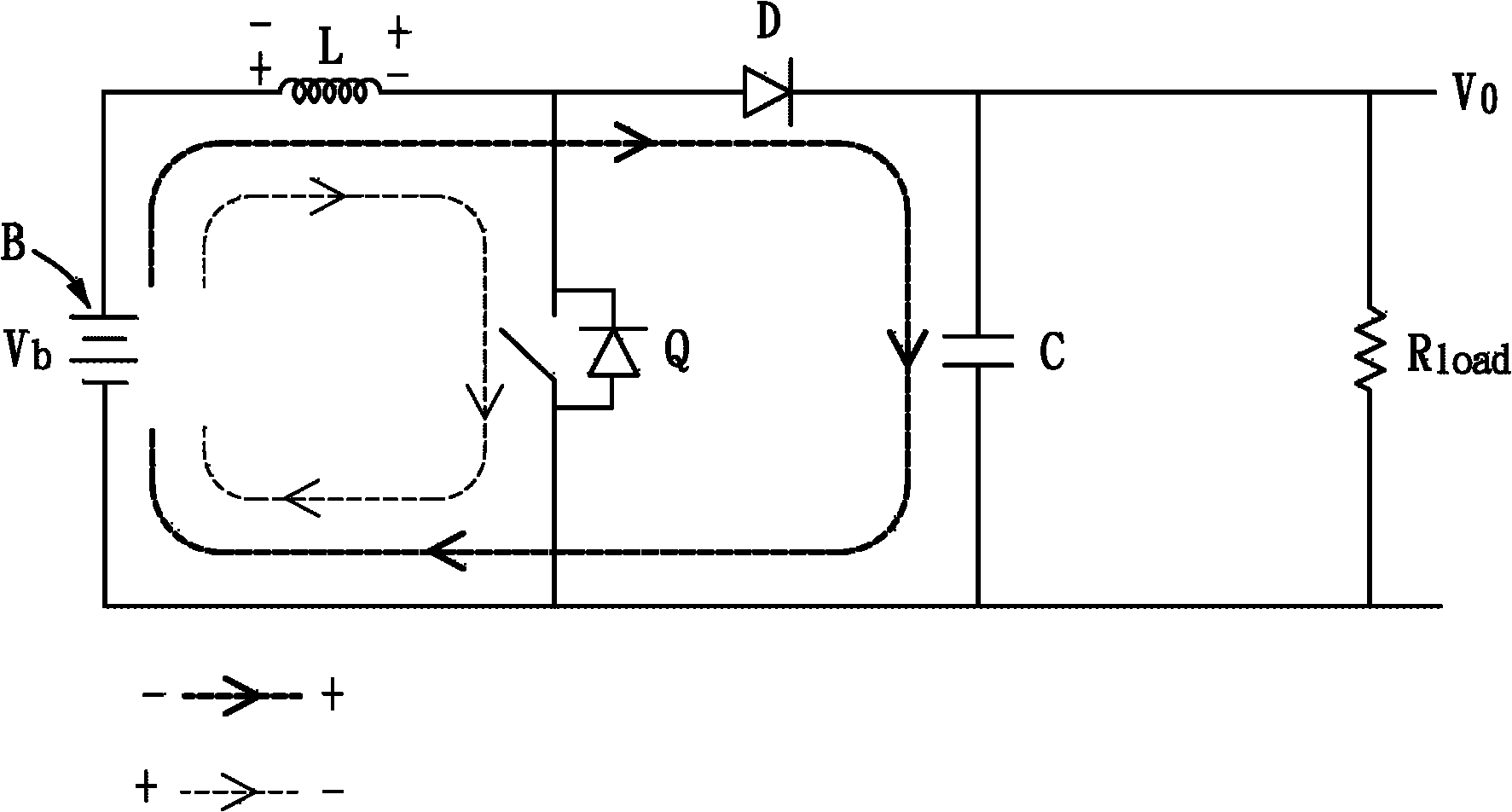
[0029] Please refer to figure 1 , is a structural schematic representation of the operating principle used in the present invention; this schematic circuit diagram is a boost converter (boost converter) circuit of a DC converter (DC to DC), including a power storage device B, an inductor L, and a switch Q, a diode D, a capacitor C, a load R1oad and an output voltage Vo.

[0030] In this circuit, the inductance L is used to temporarily store the energy converted between electric energy and magnetic field energy. When the switch Q is turned on, the voltage Vb of the power storage device B charges the inductance L, and the inductance L converts the electric energy into Magnetic fields can be stored.

[0031] At this time, the terminal volt...


PUM


Abstract

The invention discloses an electric power recharging method of a motor. The motor is electrically connected with a drive circuit and a control circuit; the drive circuit receives a control signal of the control circuit and is provided with at least two groups of switches which are connected in parallel to each other; each group of switches is formed by connecting a first switch and a second switch in series; each phase of the motor is respectively connected between the first switch and the second switch of each group of switches; and each group of switches is electrically connected with an electric power storing device or a power supply circuit. When the motor is positioned in a power generation mode, the second switch is subjected to pulse-width modulation switching on/off according to signals of various positions of a motor rotor sensed by a detection assembly positioned at the rotor position of the motor, and each first switch is always kept switching-off without switching. The invention can ensure better power generation effect and prevent a user riding in electric vehicle from generating unsmooth feeling and generating the risk when the electric power recharging method is applied to the electric vehicle.

Description

technical field [0001] The invention relates to a method for recharging electric power of a motor, in particular to an energy recovery method using a short circuit of the brushless permanent magnet motor coil, which can allow the brushless permanent magnet motor to operate without changing the existing control / drive circuit Switch between power generation mode and motor mode; in power generation mode, using different switch switching methods, the rotational kinetic energy of the brushless permanent magnet motor can be converted into electrical energy with the highest conversion efficiency and the battery can also be charged at low speed. Background technique [0002] Please refer to Figure 9 , is a link circuit diagram showing a two-phase driver drive circuit and a permanent magnet motor of a known brushless permanent magnet motor. In the power generation mode, first turn on (ON) the upper and lower switches of the driver at the same time, that is, the switches Q1 and Q4 ar...

Claims


Application Information

Patent Timeline
Patent Type & Authority Applications(China)
IPC IPC(8): H02J15/00H02P6/16H02P6/17
Inventor 朱明聪
Owner ADLEE POWERTRONIC
Why Eureka
Try Eureka