Condensate water recycling and conveying system and method thereof

A technology of condensate and delivery tanks, which is applied in steam/steam condensers, supplementary water supply, lighting and heating equipment, etc. It can solve the problems of inability to directly connect to condensate recovery, so as to prevent device stagnation and failure, reduce maintenance costs, Effect of improving work reliability

Active Publication Date: 2017-08-08
北京疏水阀门厂
View PDF8 Cites 3 Cited by
  • Summary
  • Abstract
  • Description
  • Claims
  • Application Information

AI Technical Summary

Problems solved by technology

Neither the steam (air) delivery pump nor the electric hot water pump can be directly applied to the steam heat exchange equipment or the direct connection of the steam pipe network for condensate recovery. A steam trap must be installed behind the steam heat exchange equipment or the steam pipe network. The steam trap performs a steam-water separation, and then the steam trap is connected to the condensed water recovery conveying device for use

Method used


Image

  • Condensate water recycling and conveying system and method thereof
  • Condensate water recycling and conveying system and method thereof
  • Condensate water recycling and conveying system and method thereof

Examples


Embodiment 1

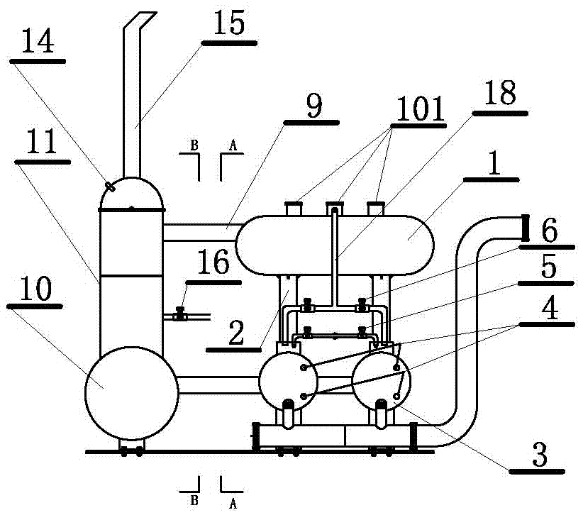
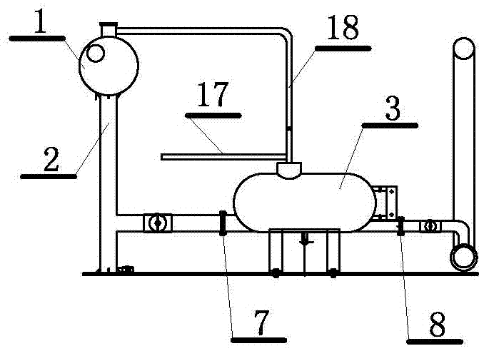
[0026] A condensate recovery delivery system such as figure 1 with figure 2As shown, the system includes a condensed water collection tank 1 connected to the main steam transmission pipeline or the high-temperature condensed water recovery pipeline through the connection port 101, and the bottom end of the water collection tank is connected to the condensate of the condensed water delivery tank 3 through the pipeline 2. There can be multiple water inlets and condensed water delivery tanks according to actual applications. The figure shows that two are provided in this embodiment, wherein a high and low liquid level double-contact electric contact liquid level gauge 4 is arranged in the condensed water delivery tank. , the upper end of the condensed water delivery tank is provided with a power gas source input port and a power gas discharge nozzle. Solenoid valve 6 discharges the power gas input in the condensate delivery tank, and the input power air presses the condensate i...

Embodiment 2

[0034] A method for collecting and discharging condensed water, more specifically, a method for collecting and discharging condensed water in a main steam transmission pipeline or a condensed water recovery pipeline; this embodiment is realized on the basis of Embodiment 1, therefore, the embodiment The content in 1 should be regarded as a supplement to this embodiment. The method is: connect a condensate water collection tank to the main steam transmission pipeline or high-temperature condensate recovery pipeline, and the bottom end of the water collection tank is connected to The condensed water inlet of the condensed water delivery tank is provided with a power gas source input port and a power gas discharge nozzle at the upper end of the condensate water transfer tank. The power gas source input port is connected to a power gas source through the first solenoid valve, and the power gas discharge pipe The power gas input in the condensed water delivery tank is discharged thr...


PUM


Abstract

The invention discloses a condensate water recycling and conveying system and a method thereof. The system comprises a condensate water collection tank connected with a steam conveying main pipeline or a high-temperature condensed water recycling pipeline. The bottom end of the water collection tank is connected with condensate water inlets of condensate water conveying tanks through pipelines. High and low liquid level double-contact electric contact liquid level meters are arranged in the condensate water conveying tanks. Power gas source input ports and power gas discharge pipe openings are formed in the upper ends of the condensate water conveying tanks. Each power gas source input port is connected with a power gas source through a first electromagnetic valve. The power gas discharge pipe openings discharge power gas, input in the condensate water conveying tanks, through second electromagnetic valves. The input power gas presses condensate water in the condensate water conveying tanks to be discharged from condensate water outlets of the condensate water conveying tanks. High liquid level contacts of the double-contact electric contact liquid level meters are connected with the first electromagnetic valves to control the power gas source to be opened and closed. Low liquid level contacts of the double-contact electric contact liquid level meters are connected with the second electromagnetic valves to control the power gas in the condensate water conveying tanks to be discharged and closed.

Description

technical field [0001] The invention relates to a condensed water recycling and conveying system and a method thereof, in particular to an efficient and environmentally friendly condensed water recycling and conveying system and a method based on electric contact liquid level gauge and electromagnetic valve control. Background technique [0002] Steam, as an indispensable power source for modern large-scale steel, chemical, and electric power industries, is being fully utilized. With the establishment of energy-saving enterprises, steam condensate recovery and reuse technology has been widely used. The existing steam condensed water recovery and reuse technology mainly includes two parts: condensed water recovery and condensed water transportation. [0003] Commonly used condensate recovery devices at this stage are divided into open recovery systems and closed recovery systems. The open recovery system is mainly used for drainage recovery of steam pipelines with different ...

Claims


Application Information

Patent Timeline
Patent Type & Authority Applications(China)
IPC IPC(8): F22D11/06F28B9/08
CPCF22D11/06F28B9/08
Inventor 洪桥发陈有为洪好花洪江涛
Owner 北京疏水阀门厂
Why Eureka
Try Eureka