Electromagnetic vibration transducer, sensing device and track state monitoring system
An electromagnetic vibration and energy-transducing device technology, which is applied in the direction of using electric/magnetic devices to transmit sensing components, convert sensor outputs, and measure devices, etc. question
- Summary
- Abstract
- Description
- Claims
- Application Information
AI Technical Summary
Problems solved by technology
Method used
Image
Examples
no. 1 example
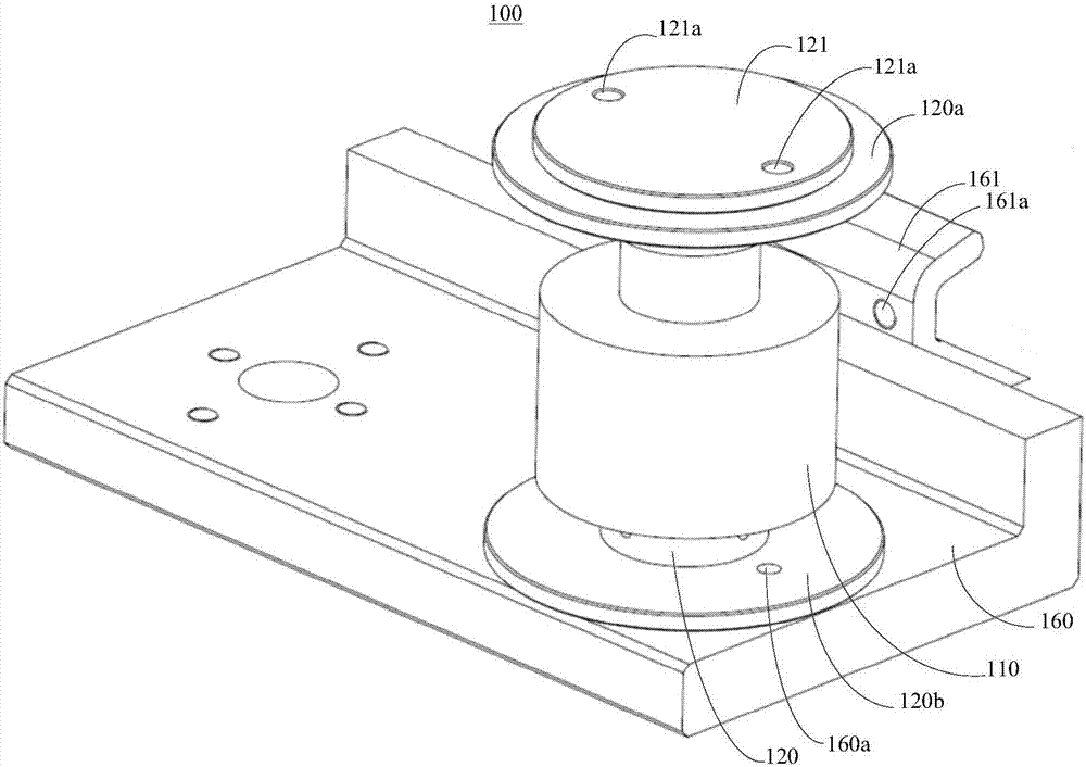
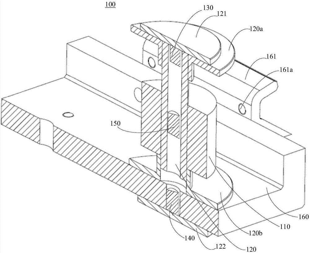
[0032] Please refer to figure 1 and figure 2, the present embodiment provides the electromagnetic vibration transducer 100 , which includes: a coil 110 , a hollow body 120 , a first magnet 130 , a second magnet 140 , and a third magnet 150 . The coil 110 is sheathed on the hollow body 120 along the axial direction of the hollow body 120 . One end of the hollow body 120 is provided with the first magnet 130 , and the other end is provided with the second magnet 140 . Under the repulsive force of the first magnet 130 and the second magnet 140 , the third magnet 150 is suspended inside the hollow body 120 . When the electromagnetic vibration transducer 100 vibrates, the third magnet 150 generates relative vibration with the first magnet 130 and the second magnet 140 , so that the coil 110 generates an induced current.
[0033] It should be noted that, when the electromagnetic vibration transducer device 100 is placed under the track of a railway, when a train passes by, the t...
no. 2 example
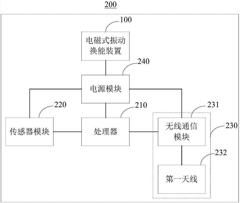
[0044] see image 3 , the present embodiment provides a sensing device 200, which includes a processor 210, a sensor module 220, a communication module 230, a power module 240, and the above-mentioned electromagnetic vibration transducer device 100. The processor 210 is electrically connected to the sensor module 220 , the communication module 230 and the power module 240 respectively. The power supply module 240 is electrically connected to the sensor module 220 , the communication module 230 , and the electromagnetic vibration transducer 100 , respectively. The power supply module 240 is used to obtain the induced current generated by the electromagnetic vibration transducer device 100 to provide power for the sensing device 200 . The sensor module 220 is used to collect data and send it to the processor 210 . The processor 210 is configured to process the received data collected by the sensor module 220 and send it to the communication module 230 . The communication modu...
no. 3 example
[0058] see Figure 6 , the present embodiment provides a track state monitoring system 300 , the system 300 includes the above-mentioned sensing device 200 , a coordinator module 310 and a server 320 . The coordinator module 310 is respectively connected to the sensing device 200 and the server 320 through a network 330 . The sensing device 200 is used to collect track state data and send it to the coordinator module 310 . Track status data may include information such as temperature and humidity around the track. The coordinator module 310 is used for sending the received track state data to the server 320 .
[0059] As an implementation manner, the coordinator module 310 includes multiple coordinators 311 . It can be understood that the coordinator 311 may include a microprocessor and a communication module electrically connected to the microprocessor. see Figure 7 , the communication module may include a ZigBee wireless communication module and a second antenna 311e e...
PUM
 Abstract
Description
Claims
Application Information
 - R&D
- Intellectual Property
- Life Sciences
- Materials
- Tech Scout
- Unparalleled Data Quality
- Higher Quality Content
- 60% Fewer Hallucinations
Browse by: Latest US Patents, China's latest patents, Technical Efficacy Thesaurus, Application Domain, Technology Topic, Popular Technical Reports.
© 2025 PatSnap. All rights reserved.Legal|Privacy policy|Modern Slavery Act Transparency Statement|Sitemap|About US| Contact US: help@patsnap.com


