Interferometric three-dimensional imaging method for space high-speed moving targets

A high-speed motion, three-dimensional imaging technology, applied in the direction of radio wave measurement systems, instruments, etc., can solve the problems of interferometric phase extraction interference, echo phase information change, interference processing, etc., to achieve the effect of realizing three-dimensional imaging and solving compensation problems

Active Publication Date: 2017-08-08
AIR FORCE UNIV PLA
View PDF3 Cites 6 Cited by
  • Summary
  • Abstract
  • Description
  • Claims
  • Application Information

AI Technical Summary

Problems solved by technology

However, space objects generally have a very high speed of motion, and high-speed movement will cause the one-dimensional range image of the target to widen and move, which will bring many adverse effects on the interference three-dimensional imaging, mainly as follows: (1) The broadening of the one-dimensional range image makes the It is difficult to extract the trajectory of each scattering point echo in the distance-slow time plane, and it is difficult to separate the echoes of each scattering point; (2) The broadening of the one-dimensional range image interferes with the interferometric phase extraction of the distance-slow time plane, directly affecting Interferometric processing; (3) The intrapulse distance walking caused by high-speed motion changes the echo phase information, and the position coordinates of the target scattering point obtained through interference processing may deviate from the actual value; (4) The one-dimensional distance caused by high-speed motion The influence of image walking is directly reflected in the reconstruction of the range coordinates of each scattering point. Since the range coordinates are directly obtained through the distance-slow time image under the far-field orthoscopic condition, the walking of the distance-slow time image will make Target scatter point radial coordinate reconstruction error

Method used


Image

  • Interferometric three-dimensional imaging method for space high-speed moving targets
  • Interferometric three-dimensional imaging method for space high-speed moving targets
  • Interferometric three-dimensional imaging method for space high-speed moving targets

Examples


example

[0089] Example: 3D imaging simulation experiment of high-speed moving target

[0090] Simulation experiment: In order to verify the effectiveness of the algorithm proposed in the present invention, we carried out the following computer simulation. The radar transmits a chirp signal, and transmits the signal in a front-to-side view. The parameter settings required for data simulation are shown in Table 1.

[0091] Table 1 Simulation parameter settings

[0092]

[0093] Simulation 1: In order to verify the effectiveness of the algorithm, the following simulation experiment is now carried out. A model of three scatter points is adopted, one of which performs spin motion, and the other two scatter points perform precession motion.

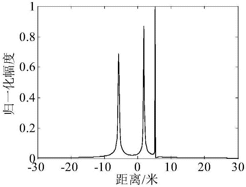
[0094] Step 1: Perform delineation and frequency tone processing on the echo signal, perform one-dimensional distance imaging, and obtain the t m = 0.62s, the distance image is shown in Figure 3(b), and Figure 3(a) is t when the radial velocity ...


PUM


Abstract

The invention provides an interferometric three-dimensional imaging method for space high-speed moving targets. The method comprises the following steps of 1, subjecting the echo signals of three antennas to translational-motion compensation and dechirping treatment, and constructing a joint parameterization sparse representation model with an unknown speed; 2, by using an improved OMP algorithm, solving the joint parameterization sparse representation model to obtain a moving speed, the location and the distance of each scattering point, and the interferometric phase information; 3, by using the obtained interferometric phase information, conducting the interference avoidance and obtaining the azimuth and the elevation position of each scattering point. Therefore, the influence of the high-speed movement of a space target is compensated. Meanwhile, the three-dimensional imaging of the space target is realized effectively.

Description

technical field [0001] The invention relates to signal and information processing technology, in particular to an interferometric three-dimensional imaging method for a space high-speed moving target. Background technique [0002] In recent years, with the increasing frequency of human exploration of space activities, the number of various space objects has increased sharply, and the space environment has become increasingly complex. Therefore, the development of space object tracking, measurement, classification, and identification is very important for ensuring my country's space security and promoting the development of national space technology. And the peaceful use of space is of great significance. [0003] Three-dimensional imaging technology can provide rich target features, and has significant advantages in obtaining the target's shape, volume, and micro-motion parameters. Therefore, the 3D imaging technology of space targets has become one of the research hotspots ...

Claims


Application Information

Patent Timeline
Patent Type & Authority Applications(China)
IPC IPC(8): G01S7/41
CPCG01S7/41
Inventor 张群孙玉雪罗迎李开明孙莉胡健
Owner AIR FORCE UNIV PLA
Why Eureka
Try Eureka