
High-order dispersion compensation and chirp spectrum widening system

A technology of dispersion compensation and chirped spectroscopy, applied in optics, nonlinear optics, instruments, etc., can solve problems such as weakening the coherence between supercontinuum and pump light source, damage to the end face of photonic crystal fiber, and large dispersion of picosecond light source , to achieve high-efficiency and high-quality optical parameter conversion, improve the ability to resist environmental interference, and realize the effect of pre-chirp compensation

Active Publication Date: 2017-08-08
UNIV OF SHANGHAI FOR SCI & TECH
View PDF7 Cites 10 Cited by
  • Summary
  • Abstract
  • Description
  • Claims
  • Application Information

AI Technical Summary

Problems solved by technology

However, the wider pulse width of the picosecond light source leads to an increase in the required pump power, which is likely to cause damage to the end face of the photonic crystal fiber, and the requirements for the end face treatment are more stringent; the use of a picosecond light source will greatly weaken the supercontinuum and the pump light source. coherence, or even completely degenerate it; on the other hand, the picosecond light source has a large second-order and third-order dispersion, and the chirp parameters are complex, and these characteristics will also be transferred to the supercontinuum optical pulse, and even deteriorate

Method used


Image

  • High-order dispersion compensation and chirp spectrum widening system
  • High-order dispersion compensation and chirp spectrum widening system
  • High-order dispersion compensation and chirp spectrum widening system

Examples


Embodiment Construction

[0025] In order to make the technical means, creative features, goals and effects of the present invention easy to understand, the following embodiments will specifically illustrate the high-order dispersion compensation chirped spectrum broadening system of the present invention in conjunction with the accompanying drawings.

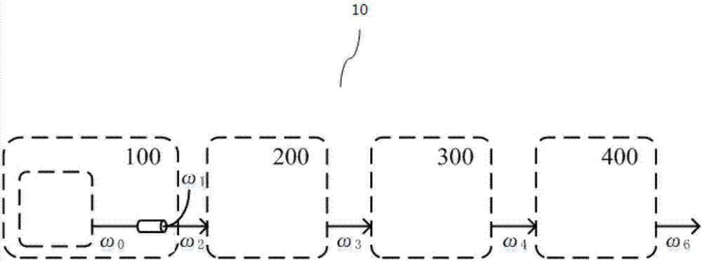
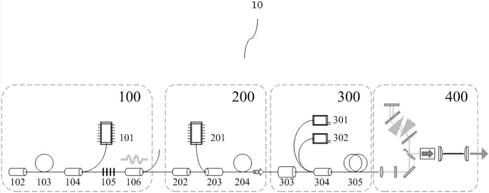
[0026] figure 1 is a simplified structural diagram of a high-order dispersion compensation chirped spectrum broadening system in an embodiment of the present invention; and figure 2 It is a structural schematic diagram of a high-order dispersion compensation and spectrum broadening device in an embodiment of the present invention.

[0027] Such as Figure 1~2 As shown, the high-order dispersion compensation chirped spectrum stretching system 10 in this embodiment includes: a pulse oscillator 100 , a fiber preamplifier 200 , a fiber main amplifier 300 , and a high-order dispersion compensation and spectrum stretcher 400 arranged in the order of optical...


PUM

PropertyMeasurementUnit
diameteraaaaaaaaaa
poweraaaaaaaaaa
wavelengthaaaaaaaaaa

Abstract

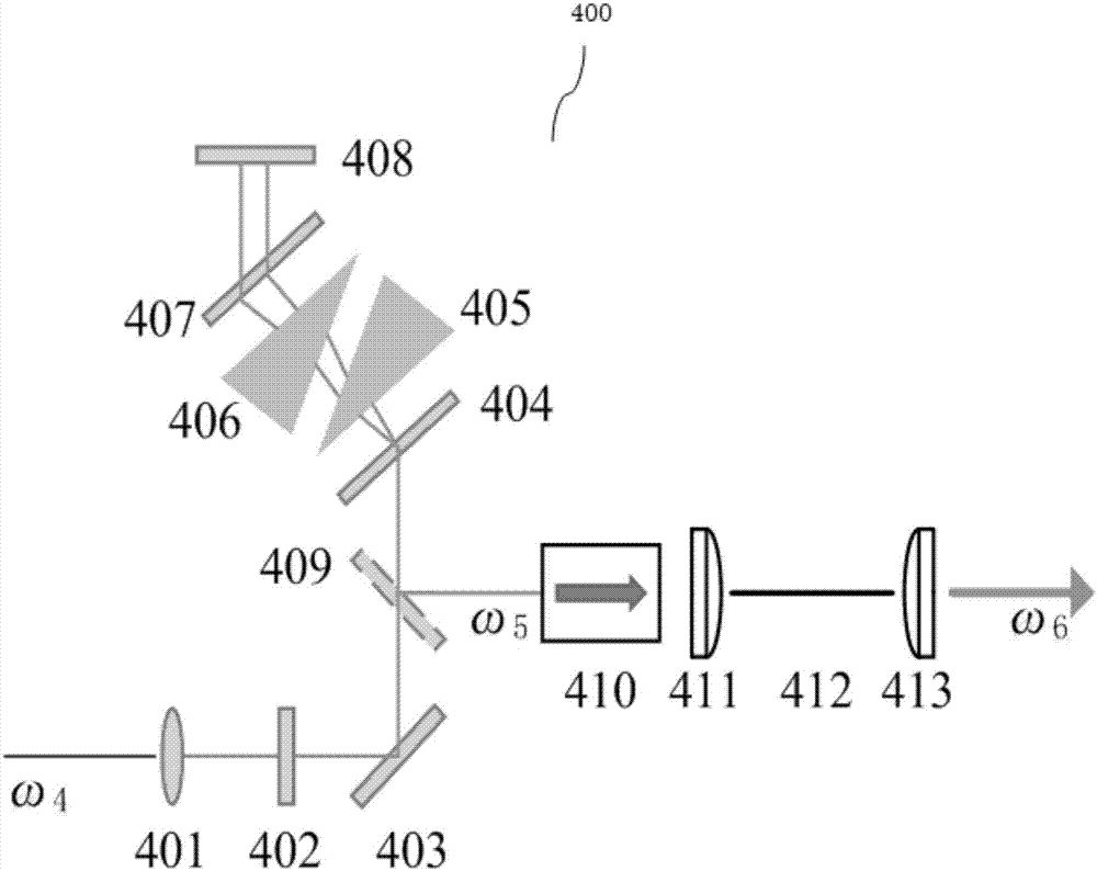
The invention provides a high-order dispersion compensation and chirp spectrum widening system. The high-order dispersion compensation and chirp spectrum widening system comprises an impulse oscillator, an optical fiber pre-amplifier, an optical fiber main amplifier and a high-order dispersion compensation and spectrum stretcher, wherein the high-order dispersion compensation and spectrum stretcher is used for performing high-order dispersion compensation and spectrum expansion on pulse which is output by the optical fiber main amplifier and amplified for the second time, and femtosecond laser pulse is obtained. The high-order dispersion compensation and spectrum stretcher comprises a first collimating lens, a half-wave plate, a first reflector, a first diffraction grating, a first diffraction prism, a second diffraction prism, a second diffraction grating, a prism square, a second reflector, a high-power space isolator, a coupling lens, a photonic crystal fiber and a second collimating lens which are arranged in an optical path sequence. With adoption of the high-order dispersion compensation and chirp spectrum widening system, high-efficiency and high-quality optical parametric conversion and ultra-wideband femtosecond pulse laser output can be realized.

Description

technical field [0001] The invention relates to the fields of ultrashort pulse laser and nonlinear optics, in particular to a high-order dispersion compensation chirp spectrum broadening system. Background technique [0002] In recent years, with the continuous improvement of the production level of fiber optic devices and gain fibers, the pulse amplification system based on double-clad doped fibers has developed rapidly. The output continuous optical power of single-mode fibers can reach 10KW. The chirp pulse amplification system has obtained a laser output with a single pulse energy of 5.7mJ, a pulse width of 200fs, and an average pulse power of 230W. In the high-power ultrashort pulse amplification system, the gain-narrowing effect and high-order dispersion mismatch are the main reasons that limit the further narrowing of the laser pulse width. Among them, the high-order dispersion of the fiber itself, the distortion of the chirped pulse shape, and the residual third-ord...

Claims


Application Information

Patent Timeline
Patent Type & Authority Applications(China)
IPC IPC(8): G02F1/35
CPCG02F1/35
Inventor 郭政儒郝强曾和平
Owner UNIV OF SHANGHAI FOR SCI & TECH
Learn More