Supercharge Your Innovation With Domain-Expert AI Agents!

A cathode frame of an electric precipitator

A cathode frame and electrostatic precipitator technology, applied in the field of electrostatic precipitator cathode frame and electrostatic precipitator, can solve problems such as the failure of the electrostatic precipitator, the enlargement of the cathode, and the short-circuit failure of the electric field.

Active Publication Date: 2019-06-18
ANHUI TECHN COLLEGE OF MECHANICAL & ELECTRICAL ENG
View PDF5 Cites 0 Cited by
  • Summary
  • Abstract
  • Description
  • Claims
  • Application Information

AI Technical Summary

Problems solved by technology

[0003] However, the cathode frame of a relatively large electrostatic precipitator has a large self-weight, and after a long running time, a certain amount of dust will accumulate on the horizontal and vertical bars of the cathode frame and the corona pole, especially when the cathode rapping device is not working properly. Normally, the dust accumulation on the corona pole line is more serious, that is, the so-called "cathode hypertrophy" phenomenon occurs, resulting in an increasing total weight of the entire cathode frame, and the entire cathode frame is completely composed of the upper part of the left and right frames. This will cause all the crossbars of the cathode frame to bend downwards and become a concave upward bow, that is, the middle part of the crossbars is most severely deformed, which will cause lateral deformation and change the relationship between the corona pole line and the anode plate. The distance between the electric precipitators will reduce the operating voltage of the electric field of the electrostatic precipitator, and the dust removal efficiency will drop sharply. Major accidents such as the cathode frame of the precipitator slipping from the cathode main support and collapsing

Method used


Image

  • A cathode frame of an electric precipitator
  • A cathode frame of an electric precipitator

Examples


Embodiment Construction

[0027] Specific embodiments of the present invention will be described in detail below in conjunction with the accompanying drawings. It should be understood that the specific embodiments described here are only used to illustrate and explain the present invention, and are not intended to limit the present invention.

[0028] In the present invention, unless stated otherwise, the orientation words included in the term such as "up, down, left, right, inside, outside, far, near" only represent the orientation of the term in the normal use state , or a common name understood by those skilled in the art, and should not be considered as a limitation of the term.

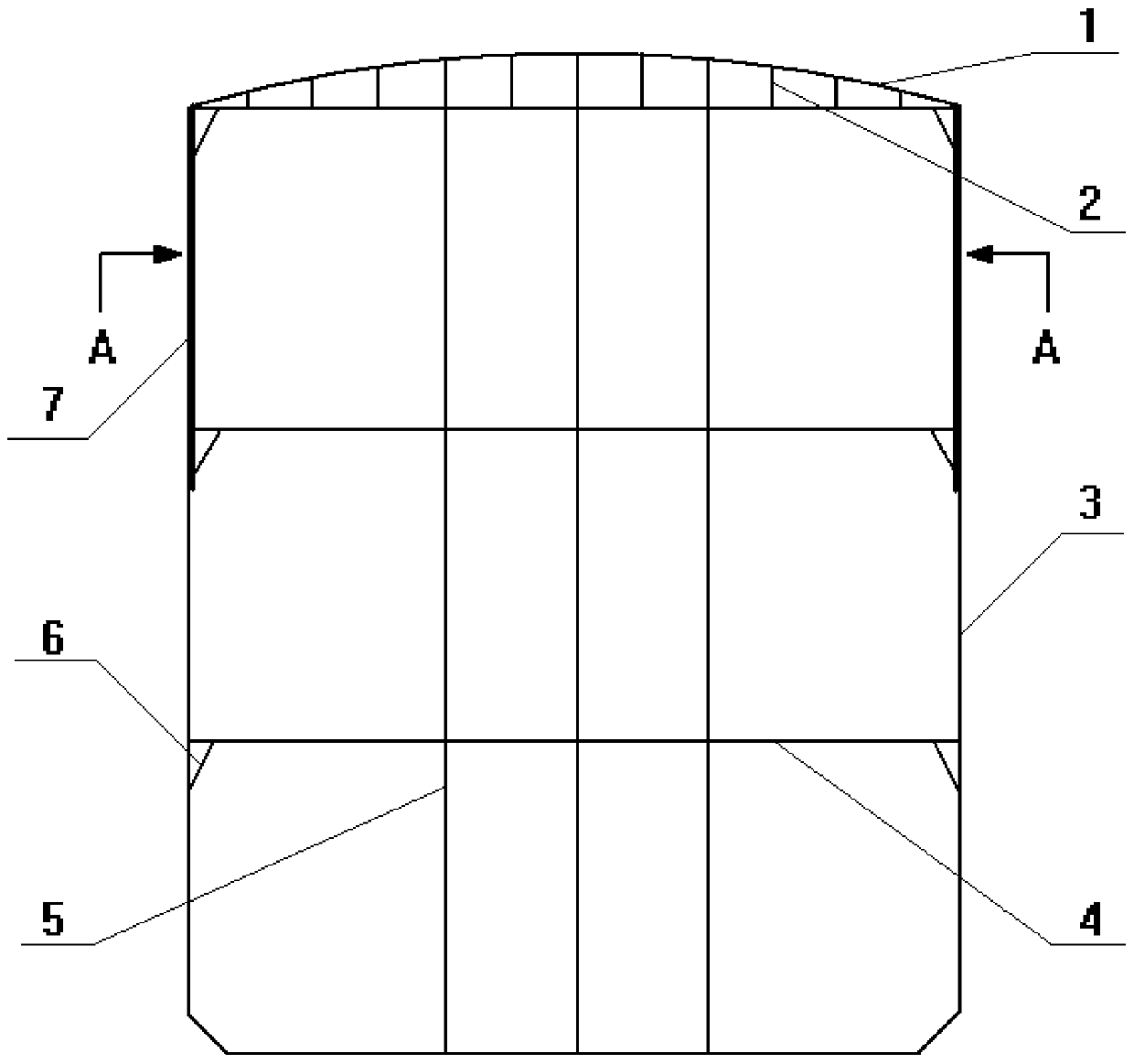
[0029] see figure 1 , the present invention provides a cathode frame for an electrostatic precipitator, comprising a rectangular frame 3 composed of four horizontal bars 4 and five vertical bars 5; The rods 4 are arranged in parallel with each other, and the five vertical rods 5 are arranged in parallel with each other;...


PUM


Abstract

The invention discloses a cathode frame for an electrostatic precipitator. The cathode frame comprises a rectangular frame formed by four cross rods and five vertical rods. The cross rods and the vertical rods are perpendicular to each other and are located in the same plane, the four cross rods are arranged in parallel with one another, and the five vertical rods are arranged in parallel with one another. The longitudinal length of the rectangular frame is divided into trisections by the four cross rods, the transverse length of the rectangular frame is divided into 2: 1: 1: 2 by the five vertical rods, and one vertical rod is located on the perpendicular center line of the rectangular frame. Upper sections of two vertical rods on the outermost side of the rectangular frame are vertical reinforcing rods, and each vertical reinforcing rod is provided with two horizontal through holes used for installing supports of the cathode frame. The cathode frame for the electrostatic precipitator is simple in structure and convenient to assemble, the situation that the cathode frame for the electrostatic precipitator is prone to bending deformation even integrally sliding down and collapsing from a main cathode supporting frame can be effectively avoided, and safety and stability of electrostatic precipitator operation are greatly improved.

Description

technical field [0001] The invention relates to a cathode system of an electric precipitator, in particular to a cathode frame of an electric precipitator, which is especially suitable for an electric precipitator with a large electric field span. Background technique [0002] Electrostatic precipitator is an environmental protection equipment that uses DC high voltage electric field to purify dust in industrial flue gas. Usually the electrode connected to the negative pole of high-voltage direct current is called corona electrode (also known as cathode), and the electrode that collects dust is called sedimentation electrode or anode (the anode must be grounded). The cathode frame is a very important part of the cathode system of the electrostatic precipitator, on which several corona electrodes are installed. Usually the cathode frame is made of seamless steel pipe into a rectangular frame, which is welded by four horizontal bars and four vertical bars; there is a support ...

Claims


Application Information

Patent Timeline
Patent Type & Authority Patents(China)
IPC IPC(8): B03C3/86B03C3/45
CPCB03C3/45B03C3/86
Inventor 曾劲松曾于汉赵祯
Owner ANHUI TECHN COLLEGE OF MECHANICAL & ELECTRICAL ENG
Features
  • R&D
  • Intellectual Property
  • Life Sciences
  • Materials
  • Tech Scout
  • Unparalleled Data Quality
  • Higher Quality Content
  • 60% Fewer Hallucinations
Learn More