Shot blasting head of aluminum profile shot blasting machine

A technology of shot blasting machine and aluminum profile, which is applied in the direction of abrasive jetting machine tool, used abrasive processing device, explosion generating device, etc. It can solve the problem of short service life, high maintenance frequency and cost of blasting head, carbon and chromium content In order to achieve the effect of increasing wear resistance and service life, preventing sand and dust from entering the inside of the bearing, and increasing the tightness of the structure

Active Publication Date: 2017-08-11
佛山市中福机械设备有限公司
View PDF7 Cites 1 Cited by
  • Summary
  • Abstract
  • Description
  • Claims
  • Application Information

AI Technical Summary

Problems solved by technology

[0002] The injection chamber of the blasting head of the shot blasting machine imported from abroad is an arc-shaped top plate and fan-shaped side plates with arc tops on both sides to form a domed inverted fan-shaped injection chamber. Cast iron produces this kind of parts, but the carbon and chromium content of this kind of parts produced by domestic wear-resistant cast iron does not meet the requirements of imported samples, and the density is low, the hardness is low after heat treatment, and the deformation is large, resulting in bursting and other scrap rates. High, short service life, and the sealing performance of the injection chamber is poor, and the parts are difficult to process after heat treatment. In addition, the injection chamber and the bearing seat of the throwing head produced abroad are separated, so that the dust flying out of the injection chamber cannot It will directly enter the bearing seat, but this causes the supporting point between the impeller and the bearing seat to be far away, and the rigidity is poor. When the blade or the impeller body is worn, it will generate greater vibration. Therefore, the maintenance frequency and maintenance cost of the throwing head are relatively high. high

Method used


Image

  • Shot blasting head of aluminum profile shot blasting machine
  • Shot blasting head of aluminum profile shot blasting machine
  • Shot blasting head of aluminum profile shot blasting machine

Examples


Embodiment Construction

[0017] The following will clearly and completely describe the technical solutions in the embodiments of the present invention with reference to the accompanying drawings in the embodiments of the present invention. Obviously, the described embodiments are only some, not all, embodiments of the present invention. Based on the embodiments of the present invention, all other embodiments obtained by persons of ordinary skill in the art without making creative efforts belong to the protection scope of the present invention.

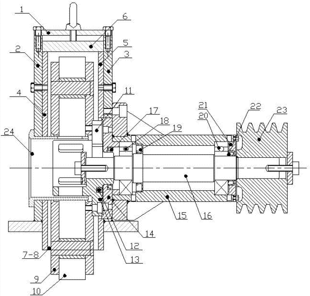
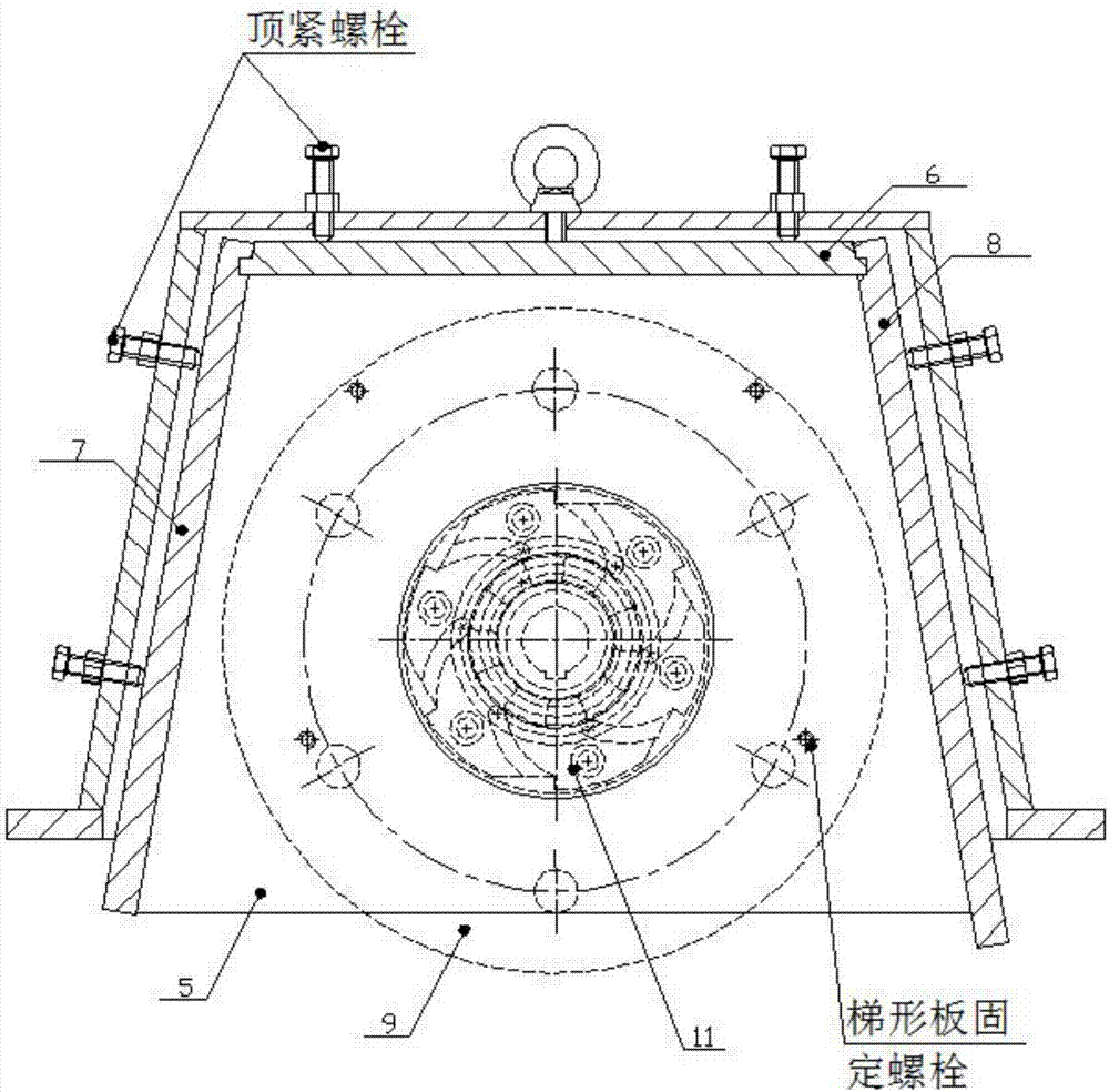
[0018] see Figure 1-4 , the present invention provides a technical solution: a throwing head of an aluminum profile shot blasting machine, comprising: a gun shell top cover 1, a gun shell front cover 2, a gun shell 3, a trapezoidal plate 4, and a trapezoidal plate 5, which are placed on the trapezoidal plate The upper circumferential top guard plate 6 and the circumferential side guard plates 7-8 on both sides of the trapezoidal plate, the circumferential top...


PUM


Abstract

Disclosed is a shot blasting head of an aluminum profile shot blasting machine. The shot blasting head of the aluminum profile shot blasting machine comprises a gun cover, a wool felt seal, a gun shell, a main shaft, an oil seal, a spiral groove seal, a trapezoidal plate A, a trapezoidal plate B and an injection chamber. The gun cover is fixedly connected with the gun shell, and an impeller is arranged inside the injection chamber of the gun shell. A sand distributing sleeve is arranged at the bottom of the gun shell, and stretches into an impeller hole of the injection chamber, a spray gun main shaft stretches into the injection chamber of the gun shell from the other end of the injection chamber, and the impeller is installed at the front end of the main shaft. The shot blasting head of the aluminum profile shot blasting machine is simple in structure, and the service life of the shot blasting head is prolonged. The sealing structure of combination of the dry wool felt ring seal, a spiral sand throwing groove and a framework oil seal is adopted, and therefore sand dust is effectively prevented from entering the interiors of bearings, the sand acidity technology is replaced by the sand blasting technology, the aluminum consumption is reduced, mechanical lines on the surfaces of aluminum profiles are effectively eliminated, the production cost is reduced, the profile surface quality is improved, treatment of fluorine in waste water is achieved, the shot blasting head can be continuously used for a long time, the maintenance cost is low, and the sealing performance of the injection chamber is greatly improved.

Description

technical field [0001] The invention relates to the field of shot blasting machines, in particular to a shot blasting head of an aluminum profile shot blasting machine. Background technique [0002] The injection chamber of the blasting head of the shot blasting machine imported from abroad is an arc-shaped top plate and fan-shaped side plates with arc tops on both sides to form a domed inverted fan-shaped injection chamber. Cast iron produces this kind of parts, but the carbon and chromium content of this kind of parts produced by domestic wear-resistant cast iron does not meet the requirements of imported samples, and the density is low, the hardness is low after heat treatment, and the deformation is large, resulting in bursting and other scrap rates. High, short service life, and the sealing performance of the injection chamber is poor, and the parts are difficult to process after heat treatment. In addition, the injection chamber and the bearing seat of the throwing hea...

Claims


Application Information

Patent Timeline
IPC IPC(8): B24C9/00B24C5/06B24C3/04
CPCB24C3/04B24C5/062B24C9/00B24C9/003Y02P10/20
Inventor 潘永源
Owner 佛山市中福机械设备有限公司
Why Eureka
Try Eureka