Tire mounting machine for non-pneumatic tire

A non-pneumatic tire and tire loading technology, which is applied in tire installation, tire parts, transportation and packaging, etc., can solve the problems of low work efficiency, low degree of automation, and inapplicability of non-pneumatic tire installation, and achieve a simple structure Effect

Inactive Publication Date: 2017-08-11
GUANGZHOU NEDONG INFORMATION TECH
View PDF7 Cites 2 Cited by
  • Summary
  • Abstract
  • Description
  • Claims
  • Application Information

AI Technical Summary

Problems solved by technology

[0003] However, the existing tire installation equipment uses inflated tires, which are not suitable for the installation of non-inflatable tires. Therefore, in many places, the non-inflatable tires are installed by manual installation. Therefore, the current installation The mode has high work intensity, low work efficiency and low degree of automation

Method used


Image

  • Tire mounting machine for non-pneumatic tire
  • Tire mounting machine for non-pneumatic tire
  • Tire mounting machine for non-pneumatic tire

Examples


Embodiment Construction

[0016] The technical solution of this patent will be further described in detail below in conjunction with specific embodiments.

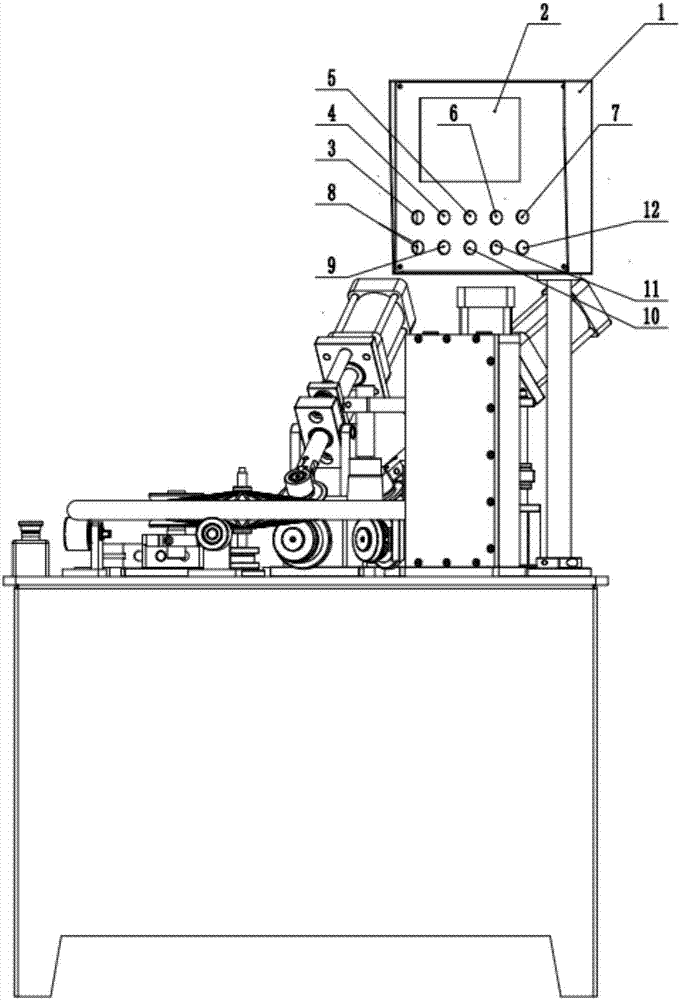
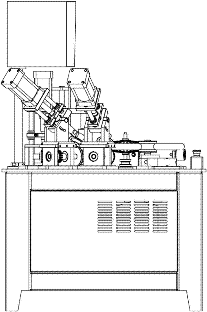
[0017] see Figure 1-4 , an air-free tire loading machine, comprising a tire loading machine body, the tire loading system of the tire loading machine body is mainly composed of supporting wheel A13, supporting wheel B14, correction wheel 15, inserting wheel B16, inserting wheel A17, pressing wheel The wheel 18 and the guide wheel 19 are formed. The support wheel A13 and the support wheel B14 are arranged on the console, and the hub is lifted by the action of the support wheel A13 and the support wheel B14 to keep the rim parallel and consistent. The machine body is equipped with a correction wheel 15, and the loaded tires are corrected and compacted through the action of the correction wheel 15. The tire loading machine body is provided with an insert wheel B16 and an insert wheel A17, and the upper station is missed by the action of the insert wh...


PUM


Abstract

The invention discloses an air-free tire loading machine. The main body of the tire loading machine has a simple structure and can be adjusted. The three devices of the correction wheel, the pressure wheel and the insertion wheel are all long strips at the installation positions, and cooperate with the adjustment wheel at the rear. This makes the tire loading machine suitable for non-pneumatic tires of various sizes. The device body is numerically controlled and adopts numerical control that meets the needs of modern industrial production. It can set the tire loading time, operation step interval, and loading time during the working process The tire process only needs one button to complete the numerically-controlled cosmetic tire installation, and the invention precisely installs the tire and adopts the double inserting wheel method. An insert wheel installs the card slot into the slot of the hub, and the correction wheel corrects the vertical deviation of the tire to complete the precise tire installation.

Description

technical field [0001] The invention relates to a tire mounting machine, in particular to an air-free tire tire mounting machine. Background technique [0002] When installing the tire, it is necessary to securely place the inner tube lining on the rim, apply talcum powder on the inner wall of the outer tire and the outer wall of the inner tube respectively, insert one side of the outer tire into the rim, and align the valve of the inner tube with the round hole of the rim Insert the inner tube from the gap between the rim and the rim, take out the valve from the round hole of the rim, put on the valve cap, and then install the other side of the tire. [0003] However, the existing tire installation equipment uses inflated tires, which are not suitable for the installation of non-inflatable tires. Therefore, in many places, the non-inflatable tires are installed by manual installation. Therefore, the current installation Mode work intensity is high, work efficiency is low, ...

Claims


Application Information

Patent Timeline
Patent Type & Authority Applications(China)
IPC IPC(8): B60C25/05B60C25/12
CPCB60C25/0503B60C25/12
Inventor 张春如
Owner GUANGZHOU NEDONG INFORMATION TECH
Why Eureka
Try Eureka