Supercharge Your Innovation With Domain-Expert AI Agents!

Weft Yarn Detection Method In Air Jet Loom

A detection method, the technology of air-jet looms, applied in looms, textiles, textiles and papermaking, etc., can solve problems such as differences, defects, and inability to detect weft yarns, and achieve the effect of reducing consumption and reducing false detections

Active Publication Date: 2017-08-11
TOYOTA IND CORP
View PDF11 Cites 2 Cited by
  • Summary
  • Abstract
  • Description
  • Claims
  • Application Information

AI Technical Summary

Problems solved by technology

However, due to the difference in the thickness of the weft yarn supplied from the yarn feeding part, even when the weft yarn is inserted under the same weft insertion condition, the timing at which the weft yarn reaches the fabric end on the opposite side differs.
[0008] If there is a difference in the arrival timing of the weft yarn, the weft yarn that is normally inserted may not be detected when the end of the weft yarn detection period is advanced.
If the weft yarn that is normally inserted cannot be detected, it will be judged as poor weft insertion regardless of whether the weft insertion is normal, and the air jet loom will be stopped.

Method used


Image

  • Weft Yarn Detection Method In Air Jet Loom
  • Weft Yarn Detection Method In Air Jet Loom
  • Weft Yarn Detection Method In Air Jet Loom

Examples


no. 1 approach

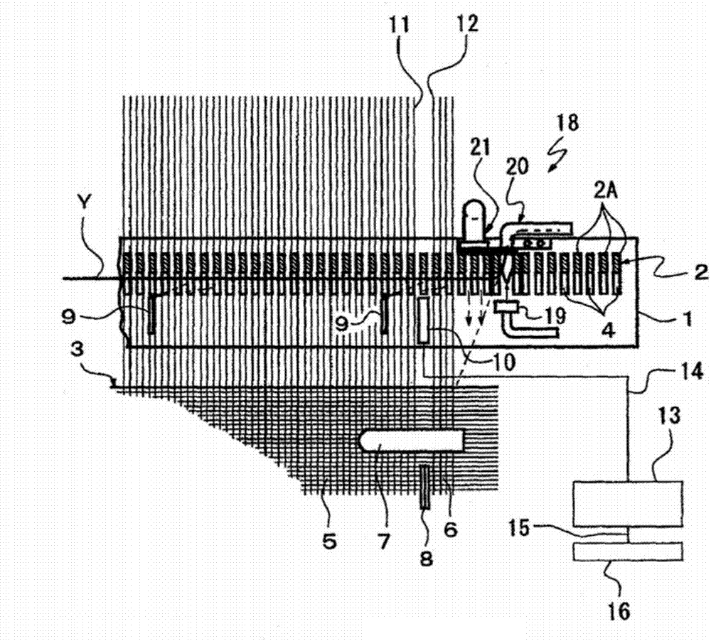
[0021] based on Figure 1 ~ Figure 3 The first embodiment will be described. figure 1 The weaving end on the side opposite to the weft insertion side of the air loom is shown.

[0022] The sley 1 is fixed to a swing shaft (not shown) via a sley foot (not shown), and can swing in the front-back direction of the loom. The deformed reed 2 composed of a plurality of dents 2A attached to the sley 1 has a weft guide passage 4 opened toward the cloth fell 3 side. A temple device 7 is arranged across the weaving end of the fabric 5 and the discarded selvedge 6 so as to straddle both.

[0023] The weft yarn Y passing between the fabric 5 and the discarded selvage 6 passing through the temple device 7 is cut by the cutting tool 8 provided between the fabric 5 and the discarded selvedge 6 . A plurality of auxiliary nozzles 9 for feeding the inserted weft yarn Y are arranged at intervals above the sley 1 .

[0024] Further, on the sley 1, a photoelectric weft sensor 10 constituting a ...

no. 2 approach

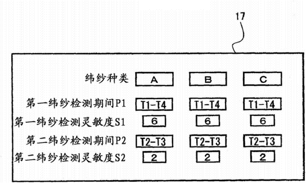
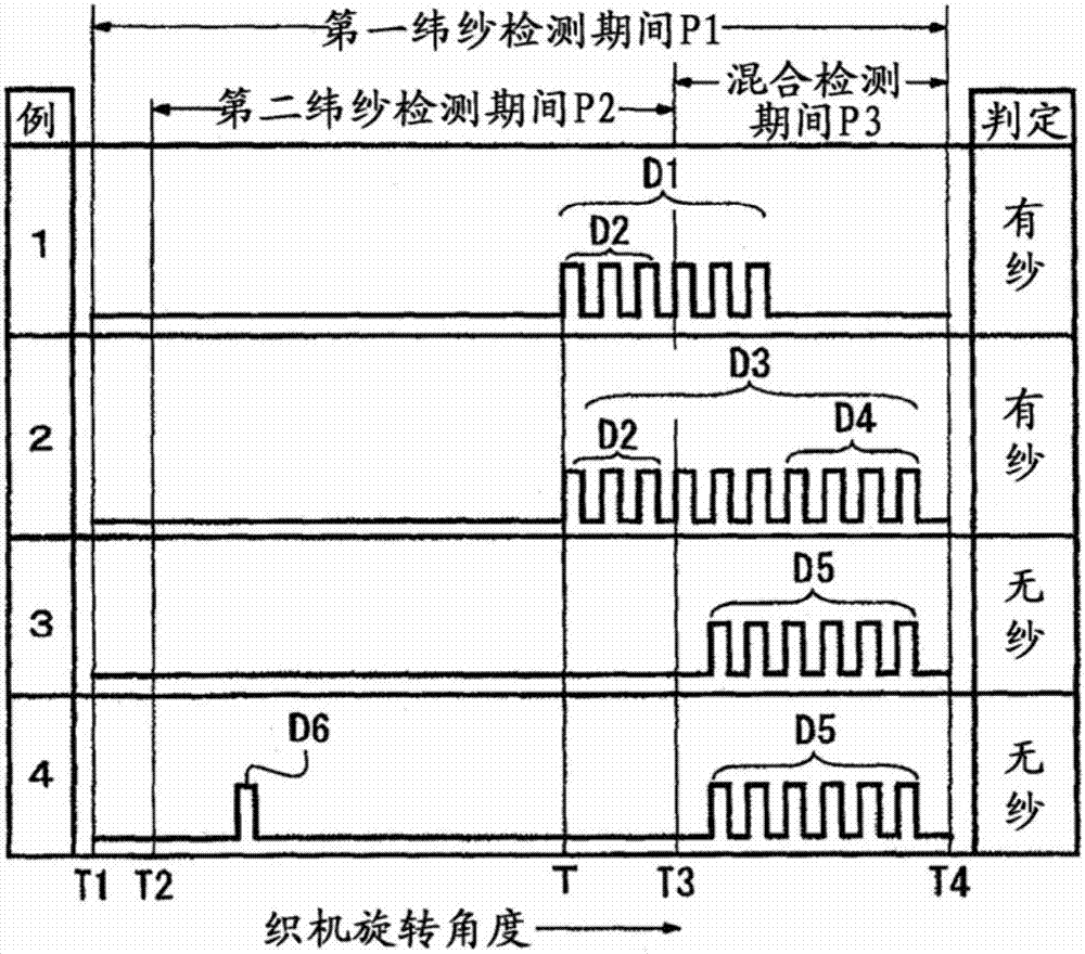
[0051] Figure 4 It is a figure which shows 2nd Embodiment, The same code|symbol is used for the same structure as 1st Embodiment, and detailed description is abbreviate|omitted. In the first embodiment, the light receiving signal of the photoelectric weft sensor 10 is converted into a pulse signal and sent, and the number of pulses is counted in the control device 13, but in the second embodiment, the photoelectric weft sensor 10 is detected in the control device 13. The configuration is for a period in which the magnitude of the transmitted light reception signal is equal to or greater than the threshold value (sensitivity).

[0052] Such as Figure 4 As shown, the first weft yarn detection period P1 and the second weft yarn detection period P2 are set in the control device 13 . The period during which the light reception signal is equal to or greater than the threshold value (sensitivity) is a period D7 in the first weft detection period P1, and a period D8 in the second ...


PUM


Abstract

The invention relates to a weft yarn detection method in an air-jet loom. Reduce false detections by photoelectric weft sensors. A first weft detection period P1 and a second weft detection period P2 are set in the photoelectric weft sensor. A first threshold (sensitivity) is set for the first weft detection period, and a second threshold (sensitivity) is set for the second weft detection period. The determination condition for the presence or absence of the weft yarn is set such that the number of pulse signals detected during the first weft yarn detection period is equal to or greater than a first threshold value (sensitivity), and that the number of pulse signals detected during the second weft yarn detection period is a second threshold value (sensitivity) In the above cases, it is determined that there is a weft yarn. The detection of the weft yarn Y can be reliably performed by a structure in which the detection of the weft yarn Y is performed in two stages, the first weft yarn detection period in which the first threshold value (sensitivity) is set and the second weft yarn detection period in which the second threshold value (sensitivity) is set. Distinguish weft yarn from warp yarn or waste selvedge yarn, reduce false detection by photoelectric weft yarn sensor.

Description

technical field [0001] The invention of the present application relates to a detection method of a weft yarn inserted into an air-jet loom. Background technique [0002] In the air-jet loom, a weft detection device for detecting whether the weft inserted has reached the weft end opposite to the weft insertion side at normal timing is provided at the weft end opposite to the weft insertion side. For example, Patent Document 1 discloses an air-jet loom in which a reflective weft yarn detection device equipped with a light-emitting element and a light-receiving element is installed between the warp yarn at the weaving end on the opposite side to the weft insertion side and the discarded selvedge yarn. invention. [0003] In the invention disclosed in Patent Document 1, in order to reduce the loss of the weft yarn due to the size of the weft yarn detection device in relation to the weaving direction, the ratio of the width of the protruding portion of the weft yarn detection de...

Claims


Application Information

Patent Timeline
IPC IPC(8): D03D47/30D03D51/34
CPCD03D47/3073D03D51/34
Inventor 牧野洋一奥田泰治郎吉野诚汤沢亮三石黑博纪
Owner TOYOTA IND CORP
Features
  • R&D
  • Intellectual Property
  • Life Sciences
  • Materials
  • Tech Scout
  • Unparalleled Data Quality
  • Higher Quality Content
  • 60% Fewer Hallucinations
Learn More