Textile printing and dyeing equipment with self-adjusting function

A textile printing and dyeing and self-regulating technology, which is applied in textiles and papermaking, textile processing machine accessories, textile material processing, etc., can solve problems such as poor dye penetration, insufficient dyeing, and lack of self-regulating functions, so as to ensure stability , Reduce the effect of fatigue damage

Inactive Publication Date: 2017-08-11
CHANGXING JIAPU YIHANG TEXTILE FACTORY
View PDF1 Cites 3 Cited by
  • Summary
  • Abstract
  • Description
  • Claims
  • Application Information

AI Technical Summary

Problems solved by technology

[0006] The purpose of the present invention is to address the deficiencies of the prior art, to overcome the lack of self-adjustment function of the equipment, and the inability to self-adjust the amount of dye injection when dealing with different thicknesses of cloth, resulting in poor dyeing effect and the existence of cloth folds during the spray dyeing process, and the dyeing is not in place and poor dye penetration

Method used


Image

  • Textile printing and dyeing equipment with self-adjusting function
  • Textile printing and dyeing equipment with self-adjusting function
  • Textile printing and dyeing equipment with self-adjusting function

Examples


Embodiment 1

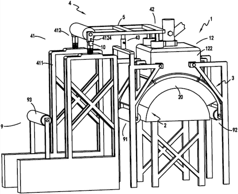
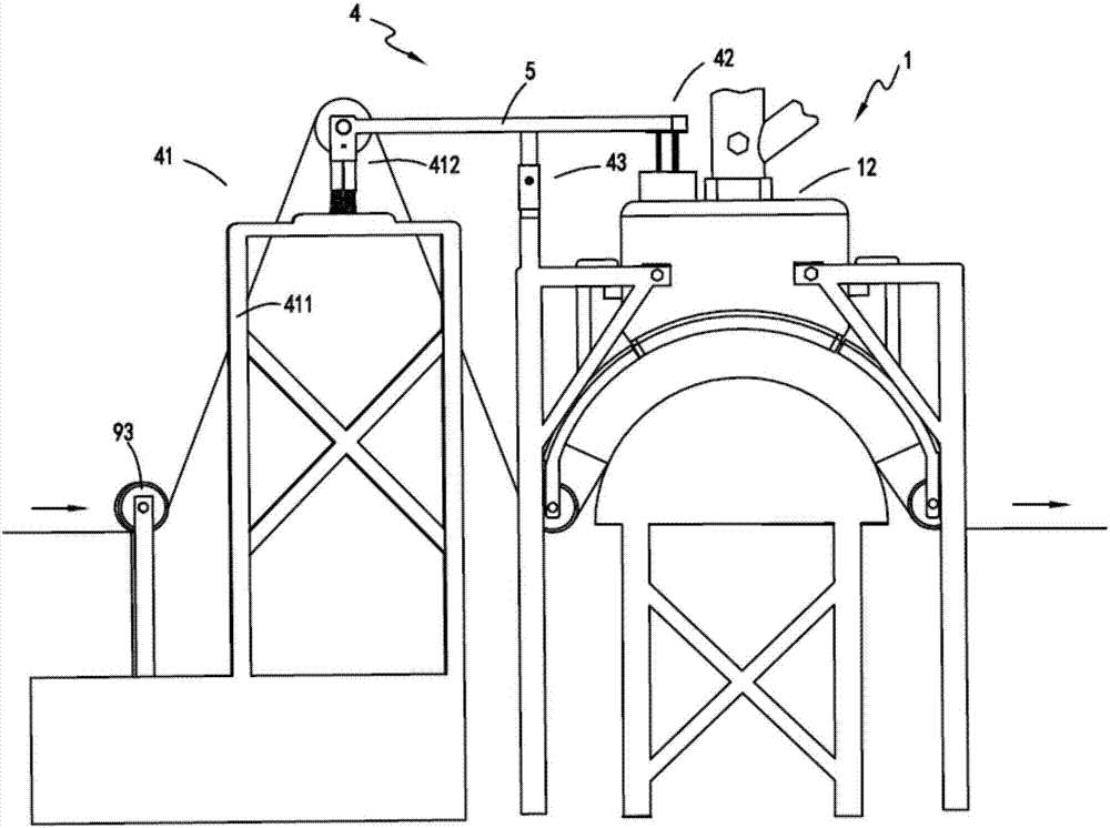
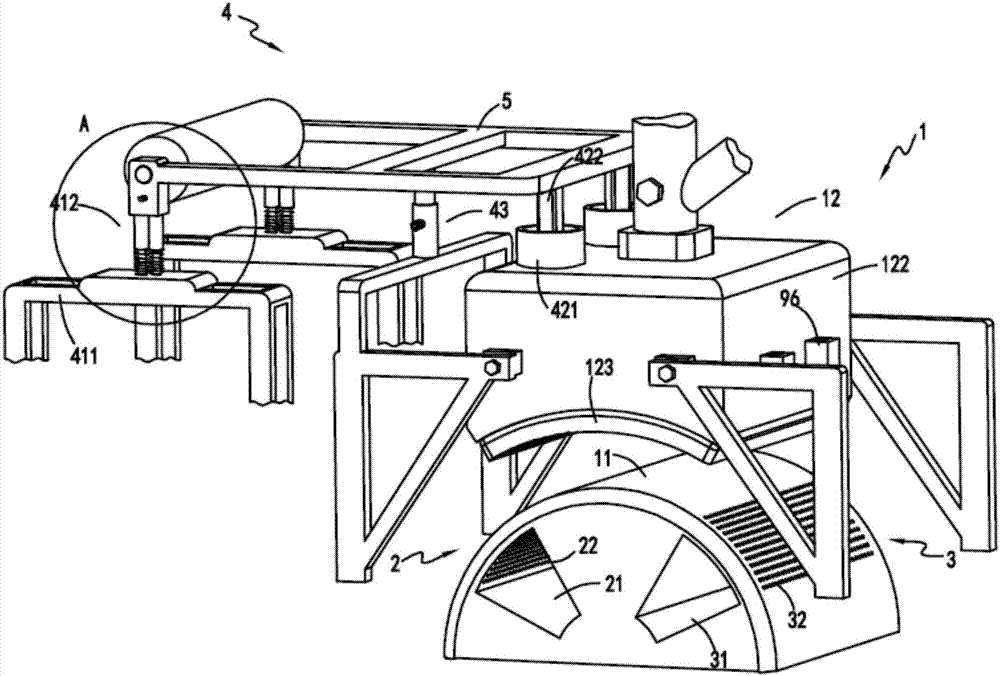
[0039] figure 1 It is a schematic diagram of the structure of textile printing and dyeing equipment with self-regulating function, figure 2 It is a schematic diagram of the front view of the textile printing and dyeing equipment with self-adjusting function, image 3 Schematic diagram of the structure of the regulation part, Figure 4 It is a partially enlarged schematic diagram of the upgrading device, Figure 5 is a schematic cutaway diagram of the spraying mechanism, Figure 6 It is a schematic diagram of the front view of the spraying mechanism and the conduction part, Figure 7 It is a schematic diagram of the structure of the wrinkle-removing part and the dye-absorbing part. Such as figure 1 , figure 2 , image 3 , Figure 4 , Figure 5 , Figure 6 , Figure 7 As shown, a kind of textile printing and dyeing equipment with self-adjusting function includes a dyeing part 1, and the dyeing part 1 includes a support area 11 and a dyeing mechanism 12 for dyeing th...

Embodiment 2

[0051] Such as figure 1 , figure 2 , image 3 , Figure 4 , Figure 5 , Figure 6 , Figure 7 As shown, the components that are the same as or corresponding to those in the first embodiment are marked with the corresponding reference numerals in the first embodiment. For the sake of simplicity, only the differences from the first embodiment will be described below. The difference between the second embodiment and the first embodiment is that: the two ends of the lifting device 412 are also provided with counterweight hooks 4124 on the rotating base 4121 for placing the counterweight code 10 .

[0052] The setting of the weight code 10 is to manually add the weight code 10 to promote the drop of the plug body 422 to achieve sufficient dyeing when the pressure in the pressure chamber 121 is insufficient due to the gravity of the cloth. the injection force.

[0053] Working process: the cloth is transferred to the adjustment part 4 through the cloth guide roller a93, and ...


PUM


Abstract

The invention relates to a textile printing and dyeing device with a self-regulating function, comprising a dyeing part, the dyeing part includes a support area and a spray dyeing mechanism for dyeing the cloth in the support area; The front end, the wrinkle-removing part is used to remove the wrinkle of the cloth before it enters the support area; the dye-absorbing part, the dye-absorbing part is arranged at the rear end of the dyeing part, and the dye-absorbing part is used to promote the absorption of the dye by the cloth; adjust part, the adjusting part is arranged above the dyeing part, and the adjusting part includes a lifting mechanism that moves up and down under the action of gravity and a pressure regulating mechanism that adjusts the pressure in the pressure chamber of the spraying mechanism driven by the lifting mechanism; The equipment cannot self-adjust the amount of dye injection when dealing with fabrics of different thicknesses, resulting in poor dyeing effects, and problems such as fabric wrinkles, incomplete dyeing and poor dye penetration during the spray dyeing process.

Description

technical field [0001] The invention relates to the technical field of textile printing and dyeing equipment, in particular to a textile printing and dyeing equipment with self-regulating function. Background technique [0002] There are generally two types of fabric dyeing techniques, painting and dip-dyeing. Exhaust dyeing method pollutes a lot and wastes materials. For dyeing, the existing dyeing equipment has uneven dyeing and dye absorption is not thorough, and the dyeing equipment cannot adjust the amount of dye injection according to the actual fabric situation, resulting in uneven spray dyeing effect. question. [0003] A Chinese utility model patent with the authorized announcement number CN203782393U discloses a high-efficiency small bath ratio open-width spray dyeing machine. Water-based; however, the device has the following problems: [0004] 1. The equipment does not have the self-adjustment function, and cannot cope with the spraying and dyeing requirements...

Claims


Application Information

Patent Timeline
Patent Type & Authority Applications(China)
IPC IPC(8): D06B1/02D06B23/00D06B5/08
CPCD06B1/02D06B5/08D06B23/00
Inventor 嵅奇
Owner CHANGXING JIAPU YIHANG TEXTILE FACTORY
Why Eureka
Try Eureka