
Post-combination grouting device and construction method of cast-in-situ pile pile end and pile side

A technology for cast-in-place piles and pile sides, which is applied to sheet pile walls, foundation structure engineering, construction, etc., can solve the problem that the amount of grouting and the grouting pressure cannot be effectively controlled, the vertical bearing capacity of cast-in-place piles is discrete, and cannot be formed. Ideal geometric slurry bubbles, etc., to achieve the effect of reducing uncertain factors, facilitating popularization and application, and simple device structure

Active Publication Date: 2019-06-18
SOUTHEAST UNIV
View PDF5 Cites 0 Cited by
  • Summary
  • Abstract
  • Description
  • Claims
  • Application Information

AI Technical Summary

Problems solved by technology

[0003] However, the conventional post-grouting technology has uncertainties and complex influencing factors in the process of pile side grouting or pile tip grouting, and the randomness of the flow direction of the pressure grout on the pile side or pile tip makes it impossible to form an ideal geometric grout. At the same time, the estimated reasonable amount of grouting and grouting pressure cannot be effectively controlled, resulting in a large dispersion of vertical bearing capacity of cast-in-place piles, so that post-grouting often fails to meet the requirements Effect

Method used


Image

  • Post-combination grouting device and construction method of cast-in-situ pile pile end and pile side
  • Post-combination grouting device and construction method of cast-in-situ pile pile end and pile side
  • Post-combination grouting device and construction method of cast-in-situ pile pile end and pile side

Examples


Embodiment Construction

[0034] The technical solution of the present invention will be further described below in conjunction with the accompanying drawings.

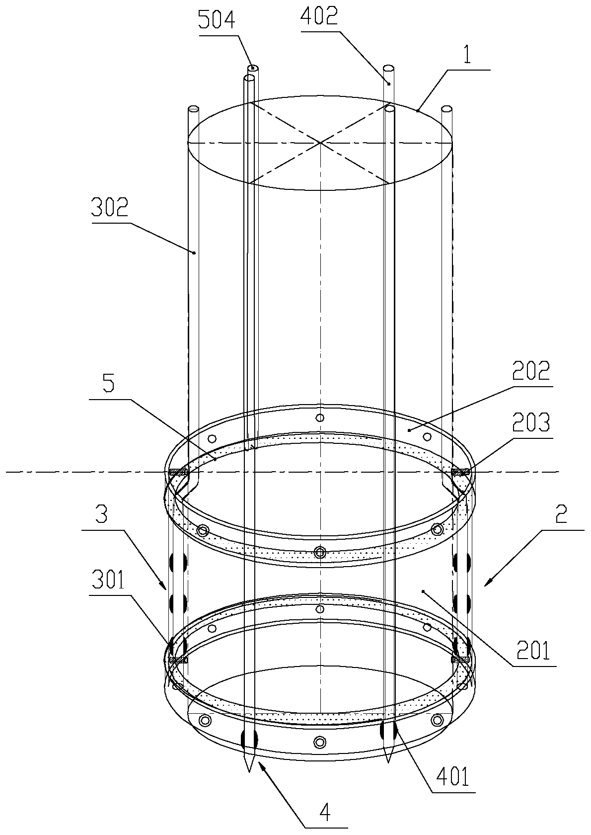
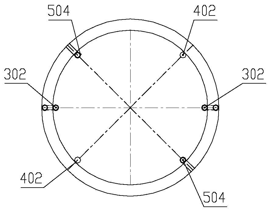
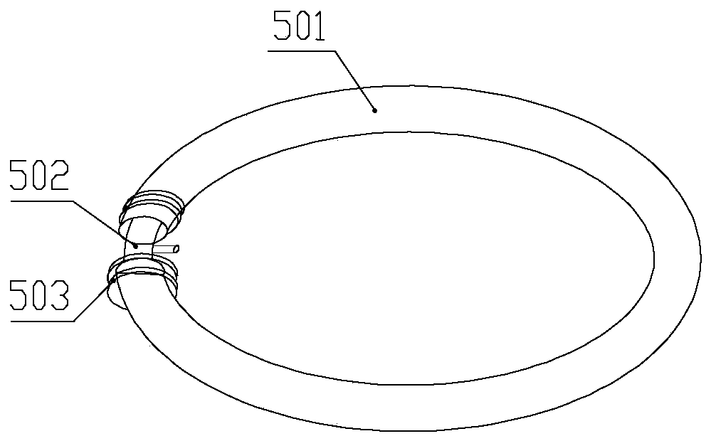
[0035] Such as figure 1 and figure 2 As shown, a post-combination grouting device for cast-in-place piles according to the present invention includes a steel cage 1 , a lateral elastic cavity 2 , a side grouting device 3 , an end grouting device 4 and a rubber airbag device 5 . Such as Figure 4 As shown, the lateral elastic cavity 2 is covered on the outside of the lower part of the steel cage 1, and the lateral elastic cavity 2 includes an elastic film 201 and a double-layer steel ring that is located at the upper and lower ends of the elastic film 201 and clamps the elastic film 201 202, the double-layer steel ring 202 is fixedly welded to the steel cage 1 through the steel bar 203, and forms a gap between the lateral elastic cavity 2 and the steel cage 1; the length of the steel bar 203 determines the size of the gap, and the steel The...


PUM


Abstract

The invention discloses a post-grouting device for a pile end and pile side combination of a cast-in-place pile. The device comprises a reinforcement cage, a lateral elastic cavity which wraps the outer side of the lower part of the reinforcement cage, a side grouting device which is fixed to the reinforcement cage and used for grouting the lateral elastic cavity, and an end grouting device for grouting the end part of the reinforcement cage, wherein the lateral elastic cavity comprises an elastic film, and double-layer steel rings which are positioned at the upper end and the lower end of the elastic film and used for clamping the elastic film; the double-layer steel rings are fixedly connected to the reinforcement through steel bars, and a clearance is formed between the lateral elastic cavity and the reinforcement cage; the reinforcement cage is sleeved with a rubber air bag device; the elastic film sleeves the rubber air bag device; the rubber air bag devices are arranged close to the upper and lower double-layer steel rings in a sleeving manner. With the adoption of the device, the bearing capacity of a pile foundation can be effectively improved; the settling amount of the pile foundation is decreased; and the cost is greatly decreased. The device is simple in structure, reasonable in construction method, convenient to operate, safe, reliable, suitably mounted at a construction site, and convenient to popularize and apply.

Description

technical field [0001] The invention relates to a grouting device for cast-in-situ piles in the field of civil engineering and a construction method thereof, in particular to a grouting device for post-combination pile ends and sides of cast-in-situ piles and a construction method thereof. Background technique [0002] Cast-in-situ piles are the most commonly used foundation form for building bridges. Because of their advantages such as flexible selection, no seasonal restrictions on construction, and less environmental pollution, this foundation form is more and more widely used. However, due to the disturbance of the soil around the pile and the bearing layer at the pile tip during the construction of the cast-in-place pile, the mud skin on the pile side and the sediment at the pile tip are generated, which affects the quality of the pile body and greatly reduces the bearing capacity of the pile foundation. The post-grouting technology can improve the above problems, incre...

Claims


Application Information

Patent Timeline
Patent Type & Authority Patents(China)
IPC IPC(8): E02D5/36E02D15/04
CPCE02D5/36E02D15/04
Inventor 戴国亮万志辉邓会元龚维明
Owner SOUTHEAST UNIV
Learn More