
Biomass semi-gasification furnace provided with ignition tubes

A kind of ignition tube and semi-gasification technology, which is used in household stoves/stoves, combustion of solid fuels, and transportation of non-flammable liquids/gases. , to achieve the effect of not easy to extinguish and smoke, easy to use and maintain, and good gasification effect

Pending Publication Date: 2017-08-11
三河市亿亚能源设备制造有限公司
View PDF6 Cites 1 Cited by
  • Summary
  • Abstract
  • Description
  • Claims
  • Application Information

AI Technical Summary

Problems solved by technology

However, the traditional biomass semi-gasifier has the following technical defects: 1. During the combustion process of the traditional gasifier, a large amount of tar containing cancer-reducing substances is produced, causing invisible damage to the user's body; 3. The density of raw materials is high; 4. It is easy to turn off the flame and smoke during the combustion process; 5. The air distribution is unreasonable, the firepower is small, and the combustion is not sufficient; 6. The structure is complex, heavy, and not portable enough

Method used


Image

  • Biomass semi-gasification furnace provided with ignition tubes
  • Biomass semi-gasification furnace provided with ignition tubes
  • Biomass semi-gasification furnace provided with ignition tubes

Examples


Embodiment Construction

[0015] The specific structure, operation method and implementation method of the present invention will be discussed in detail below in conjunction with the accompanying drawings and embodiments.

[0016] The orientation terms such as up, down, left, right, front and rear in this application document are established based on the positional relationship shown in the drawings. If the drawings are different, the corresponding positional relationship may also change accordingly, so this should not be understood as limiting the scope of protection.

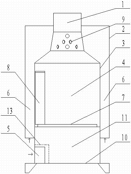
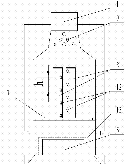
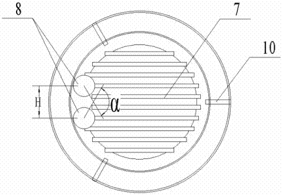
[0017] as attached figure 1 As shown, a kind of biomass semi-gasification furnace with ignition tube according to the present invention, the furnace body is a concentric double-layer structure, including an outer furnace body 2 and an inner furnace body 3, and the outer furnace body 2 and the inner furnace body The main body of 3 is a cylinder, the inner furnace body 3 is arranged inside the outer furnace body 2, and the secondary air...


PUM


Abstract

The invention discloses a biomass semi-gasification furnace provided with ignition tubes. The biomass semi-gasification furnace comprises an outer furnace body and an inner furnace body. A secondary air channel is formed between the outer furnace body and the inner furnace body. A material adding and combustion opening is formed in the top of the inner furnace body. A gasification chamber is formed in the middle of the inner furnace body, and a ventilation chamber is formed in the lower portion of the inner furnace body. A fire grate is arranged between the gasification chamber and the ventilation chamber. A base is arranged at the bottom of the ventilation chamber. A primary air inlet is formed in the position, close to the bottom, of one side of the ventilation chamber. The ignition tubes are vertically arranged at the positions, above the primary air inlet, of one side of the gasification chamber. The ignition tubes are arranged in a manner that the ignition tubes are in close proximity to the inner wall of the inner furnace body. Secondary air inlets communicating with the secondary air channel are formed below the material adding and combustion opening and above the gasification chamber. Each ignition tube is provided with multiple ignition air inlets from top to bottom. By means of the biomass semi-gasification furnace, ignition can be conducted easily; the gasification effect is good; by means of the design of the double ignition tubes, it is guaranteed that in the gasification combustion and material adding processes, the phenomena of flameout and smoking are not likely to be generated, and high efficiency and cleanliness are achieved; and the biomass semi-gasification furnace is simple in structure, easy to manufacture, convenient to use and maintain, small in weight, attractive in appearance and capable of being carried outdoors conveniently.

Description

technical field [0001] The invention relates to a biomass semi-gasification furnace, in particular to a semi-gasification furnace with a fire pipe. Background technique [0002] The development of the biomass stove industry is related to the living quality and health of 700 million farmers in my country, and has established a clean development model for developing countries. Biomass solidified briquette fuel is used for cooking and heating, which is of great significance to promoting circular economy, building an ecological society, and realizing a low-carbon economy. It is currently the best choice to replace coal burning. The development of high-efficiency and low-emission biomass stoves can promote the development of rural innovative industries, increase farmers' income, stimulate the rural economy, increase jobs, and promote the construction of a new socialist countryside. [0003] Biomass semi-gasification furnace burns biomass fuel in the furnace, and conducts reasona...

Claims


Application Information

Patent Timeline
Patent Type & Authority Applications(China)
IPC IPC(8): F24B1/02F23B90/06F23K3/16F23L9/00
CPCF23B90/06F23K3/16F23L9/00F24B1/026
Inventor 张凝王兆军
Owner 三河市亿亚能源设备制造有限公司
Learn More