Vibration monitoring system for engine's high temperature crankcase

A vibration monitoring system and engine technology, applied to vibration measurement in solids, measuring vibration, measuring devices, etc., can solve the problems of increasing test cost and difficulty, high-temperature sensors are expensive, monitoring, signal processing and fault diagnosis are difficult

Active Publication Date: 2017-08-11
SICHUAN AEROSPACE ZHONGTIAN POWER EQUIP CO LTD
View PDF6 Cites 4 Cited by
  • Summary
  • Abstract
  • Description
  • Claims
  • Application Information

AI Technical Summary

Problems solved by technology

[0002] The rear bearing of the micro-turbojet engine is in a high-temperature zone. Monitoring the vibration of the rear bearing is the best choice in theory. The difficulty lies in overcoming the influence of high temperature. The best monitoring point is on the thin-walled casing. According to actual measurements, its wall temperature is as high as 600°C Above, the high-temperature sensor is expensive, and the frequency response range is greatly narrowed, and the cost performance is low. Since the casing is a thin-walled structure, it is very difficult for the sensor to be glued or threaded. Direct testing increases the cost and difficulty of testing. Due to the high temperature Due to the influence of sensor charge components, the performance will be greatly shifted, and the test effect is difficult to guarantee. Therefore, it is difficult and necessary to carry out rear bearing vibration monitoring, signal processing and fault diagnosis.

Method used


Image

  • Vibration monitoring system for engine's high temperature crankcase
  • Vibration monitoring system for engine's high temperature crankcase
  • Vibration monitoring system for engine's high temperature crankcase

Examples


Embodiment

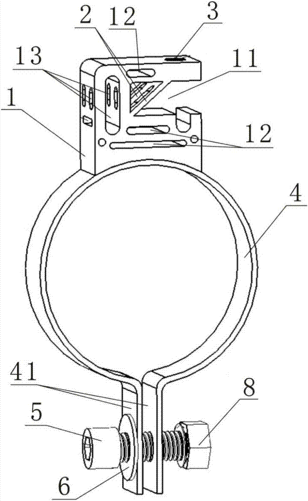
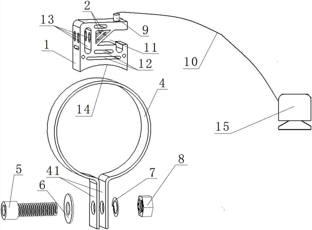
[0020] Such as figure 1 , figure 2 , image 3 As shown, a vibration monitoring system for high-temperature casing of an engine includes a cooling mounting table 1 and a clamp band 4, the clamp band 4 forms a non-closed circular shape, and the lower end of the clamp band 4 has a non-closed connection The end 41 has a bolt hole on the non-closed connection end 41, and a bolt 5 is installed in the bolt hole of the non-closed connection end 41, and the bolt 5 passes through the bolt hole of the non-closed connection end 41 and is threadedly connected with the nut 8, A number of spring washers 7 are set on the bolt 5; the bottom of the heat dissipation installation platform 1 has an arc-shaped installation end surface 14, and the arc-shaped installation end surface 14 of the heat dissipation installation platform 1 is fixedly connected with the top of the clamp band 4, and the middle part of the heat dissipation installation platform 1 There is a heat insulation slot 11, and sev...


PUM


Abstract

The invention discloses a vibration monitoring system for an engine's high temperature crankcase. The system comprises a heat radiation installation station and a clamp ring belt. The lower end of the clamp ring belt is provided with a non-closed connection end with a bolt hole. In the bolt hole, a bolt is arranged cooperatively. The bolt is sleeved by a spring shim. The circular arc shaped installation end face at the bottom of the heat radiation installation station is fixedly connected with the top of the clamp ring belt. The middle part of the heat radiation installation station is provided with a heat isolation empty groove. The heat isolation empty groove of the heat radiation installation station is connected with a biased reinforced bar in a biased manner. The heat radiation installation station is provided with heat radiation holes. The top of the heat radiation installation station is provided with a vibration sensor. The vibration sensor is in electrical communication with an acquiring and analyzing system through data lines. According to the invention, the system is provided with a vibration sensor heat radiation support with self-adaptive compensation function for heat incurred deformation, and the sensor installation station is provided with heat radiation and weight losing holes, which can radiate heat effectively and provide a suitable mechanical environment for the installation of the sensor. The vibrations signal detected by the sensor is used for heads-up on one hand; and for fault diagnosis on the other hand.

Description

technical field [0001] The invention relates to the technical field of vibration testing and fault diagnosis of high-temperature casings, in particular to a vibration monitoring system for high-temperature casings of engines. Background technique [0002] The rear bearing of the micro-turbojet engine is in a high-temperature zone. Monitoring the vibration of the rear bearing is the best choice in theory. The difficulty lies in overcoming the influence of high temperature. The best monitoring point is on the thin-walled casing. According to actual measurements, its wall temperature is as high as 600°C Above, the high-temperature sensor is expensive, and the frequency response range is greatly narrowed, and the cost performance is low. Since the casing is a thin-walled structure, it is very difficult for the sensor to be glued or threaded. Direct testing increases the cost and difficulty of testing. Due to the high temperature Due to the influence of sensor charge components, ...

Claims


Application Information

Patent Timeline
Patent Type & Authority Applications(China)
IPC IPC(8): G01H1/12
CPCG01H1/12
Inventor 李纪永陈溯刘驰
Owner SICHUAN AEROSPACE ZHONGTIAN POWER EQUIP CO LTD
Why Eureka
Try Eureka