
Material Removal Method Based on STL Model in Geometric Simulation of NC Machining

A model and geometry technology, applied in the field of virtual NC machining, can solve the problems of low machining efficiency, large errors, and poor real-time performance

Active Publication Date: 2019-09-27
TSINGHUA UNIV
View PDF6 Cites 0 Cited by
  • Summary
  • Abstract
  • Description
  • Claims
  • Application Information

AI Technical Summary

Problems solved by technology

[0006] In view of the above problems, the purpose of the present invention is to provide a material removal method based on the STL model in the geometric simulation of numerical control machining. The algorithm overcomes the problems of poor real-time performance, low processing efficiency, and large errors, and can effectively improve the processing simulation speed and accuracy

Method used


Image

  • Material Removal Method Based on STL Model in Geometric Simulation of NC Machining
  • Material Removal Method Based on STL Model in Geometric Simulation of NC Machining
  • Material Removal Method Based on STL Model in Geometric Simulation of NC Machining

Examples


Embodiment Construction

[0037] The present invention will be described in detail below in conjunction with the accompanying drawings and embodiments.

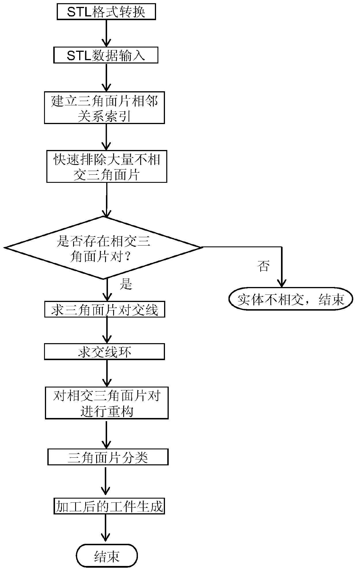
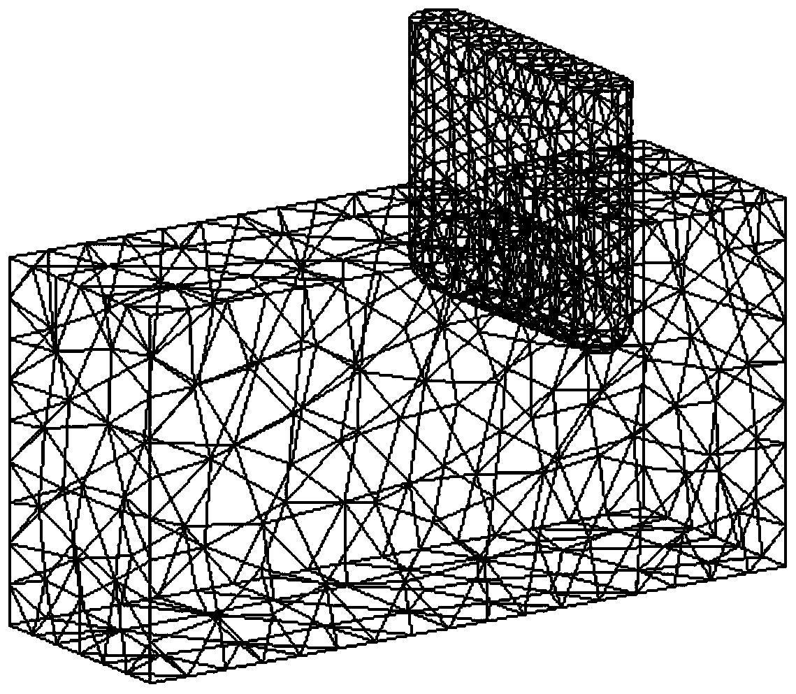
[0038] Such as figure 1 As shown, the present invention provides a material removal method based on the STL model in the geometric simulation of numerical control machining. Line segments and intersection rings; the workpiece to be machined and the sweeping tool model are both in STL format, and a boundary line will be generated when the sweeping tool cuts the workpiece. The overall structure is as follows figure 2 shown, from image 3 It can be seen that the boundary line produced by the tool sweep body cutting the workpiece is a closed loop; the closed loop divides the processed workpiece and the tool sweep body into two parts. Concrete steps of the present invention are as follows:

[0039] 1) Convert the processed workpiece and tool sweep body generated by CAD into STL format, as shown in the attached Figure 4a , Figure 4b , Figure 5a wi...


PUM


Abstract

The invention relates to an STL-model-based material removal algorithm in numeral control machining geometric simulation, comprising the following steps: transforming a CAD-generated processed workpiece and a tool swept volume into the STL format; accessing the STL models of the tool swept volume and the processed workpiece; establishing the relationship index for the triangular patches of the tool swept volume and the processed workpiece surface; establishing the smallest-possible enclosing boxes for the workpiece and the tool swept volume; screening and removing the non-intersecting triangular patches; using the dot product and the cross product of vector to create a vector determining model; determining whether the triangular patches intersect to obtain a set of intersecting triangular patch pairs; solving the intersecting lines of the intersecting triangular patch pairs; solving the intersecting line ring; reconstructing the triangular patches involved in the intersecting of the processed workpiece and the tool swept volume; classifying the triangular patches; and with the kept surface of the processed workpiece and the surface involving in the processing of the tool swept volume form a new enclosed surface to develop a workpiece model after the materials are removed.

Description

technical field [0001] The invention relates to the field of virtual numerical control machining, in particular to a material removal method based on an STL model in geometric simulation of numerical control machining. Background technique [0002] Cutting simulation and material removal simulation is one of the most important and core parts in the virtual CNC machine tool simulation system, and it is also the most difficult part to realize. The fidelity of cutting simulation depends on material removal simulation. At present, there are several representative methods at home and abroad that are widely used in geometric simulation of NC machining: [0003] The solid geometry modeling method generates the tool scanning volume by moving the tool along the machining path, and then directly subtracts the tool scanning volume from the blank body by using the Boolean difference operation. It directly uses mathematical methods such as parametric equations to describe geometry, and ...

Claims


Application Information

Patent Timeline
Patent Type & Authority Patents(China)
IPC IPC(8): G05B17/02
Inventor 关立文王立平戴玉喜
Owner TSINGHUA UNIV
Learn More