Inductor component

A technology for inductors and components, applied in the field of inductor components, can solve the problems of reduced installation stability of inductor components, unstable posture of inductor components, and small volume of magnetic complexes, and achieves suppression of volume reduction, posture stability, The effect of improving installation stability

Active Publication Date: 2017-08-11
MURATA MFG CO LTD
View PDF13 Cites 39 Cited by
  • Summary
  • Abstract
  • Description
  • Claims
  • Application Information

AI Technical Summary

Problems solved by technology

[0013] Then, it can be seen that when this inductor component is mounted, the mounting stability of the inductor component may decrease.
Specifically, in this inductor component, the exposed end surfaces of the internal electrodes serve as external terminals, but when the area of ​​the end surfaces of the internal electrodes is small relative to the width of the inductor component, when the end surfaces of the internal electrodes are joined by solder , the posture of the inductor part may become unstable
On the other hand, if the area of ​​the end faces of the internal electrodes is increased, the volume of the magnetic composite is correspondingly small, so there is a problem that the characteristics are lowered.

Method used


Image

  • Inductor component
  • Inductor component
  • Inductor component

Examples


no. 1 approach

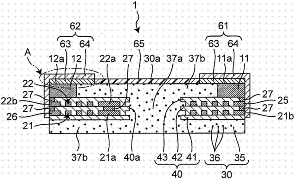
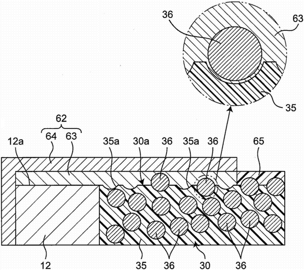
[0064] figure 1 It is a sectional view showing the first embodiment of the inductor component of the present invention. In addition, the drawings are schematic diagrams, and the scale and relationship of dimensions of components may differ from actual ones. The inductor component 1 is mounted in electronic devices such as personal computers, DVD players, digital cameras, TVs, mobile phones, and automotive electronics, for example, and has a rectangular parallelepiped shape as a whole. However, the shape of the inductor component 1 is not particularly limited, and may be a columnar shape, a polygonal columnar shape, a conical trapezoidal shape, or a polygonal pyramidal trapezoidal shape.

[0065] Such as figure 1 As shown, the inductor component 1 has multilayered spiral wirings 21 and 22 , an insulator 40 including multilayered insulating layers 41 to 43 alternately laminated with the multilayered spiral wirings 11 and 12 , and a magnetic composite covering the insulator 4...

no. 1 example

[0115] Examples of the first embodiment will be described. The inductor part is used as a step-down switching regulator with a switching frequency of 100MHz. It is a power inductor with a size of 1mm×0.5mm and a thickness of 0.23mm. The number of turns of the spiral wiring is 2.5 turns in a double-layer structure, and the inductance value is approximately 5nH at 100MHz.

[0116] The number of turns of the spiral wiring is set so that the desired inductance value can be obtained in accordance with the switching frequency. For the switching frequency of 40MHz to 100MHz, set it to be less than 10 turns.

[0117] Although the spiral wiring shows an example where L / S / t=70 / 10 / 70 μm, L and t are set according to the chip size and the allowable current energized in the inductor. The interlayer pitch of each spiral wiring is the same as the wiring pitch of 10 μm. By making the wiring pitch and interlayer pitch of the spiral wiring very narrow to 10 μm or less, the spiral wiring can b...


PUM

PropertyMeasurementUnit
particle sizeaaaaaaaaaa
thicknessaaaaaaaaaa
particle sizeaaaaaaaaaa

Abstract

An inductor component has a plurality of layers of spiral wirings a magnetic composite body directly or indirectly covering the plurality of layers of spiral wirings and made of a composite material of a resin and a metal magnetic powder with an average particle diameter of 5 mum or less an internal electrode embedded in the magnetic composite body with an end surface exposed from an outer surface of the magnetic composite body, the internal electrode being electrically connected to the spiral wirings, and an external terminal disposed on the outer surface of the magnetic composite body and electrically connected to the internal electrode.

Description

technical field [0001] The present invention relates to inductor components. Background technique [0002] Conventionally, as an inductor component, there exists what is described in Unexamined-Japanese-Patent No. 2013-225718 (patent document 1). This inductor component has a glass epoxy substrate, spiral wiring provided on both surfaces of the glass epoxy substrate, insulating resin covering the spiral wiring, and upper and lower core wires covering the insulating resin. The core wire is a resin containing metal magnetic powder, and the core wire contains metal magnetic powder with an average particle diameter of 20-50 μm. [0003] Patent Document 1: Japanese Patent Laid-Open No. 2013-225718 [0004] However, with the high performance of PCs and servers, and the popularization of mobile devices, the demand for power-saving technology has increased. IVR (Integrated Voltage Regulator: Integrated Voltage Regulator) technology has become Electronization technology is attract...

Claims


Application Information

Patent Timeline
Patent Type & Authority Applications(China)
IPC IPC(8): H01F17/00H01F27/29H01F27/30H01F27/32H01F41/06H01F41/12
CPCH01F17/0013H01F27/29H01F27/306H01F27/32H01F27/323H01F41/041H01F41/12H01F41/122H01F2017/0073H01F17/04H01F27/292H01F2017/048
Inventor 工藤敬实滨田显德大谷慎士
Owner MURATA MFG CO LTD
Why Eureka
Try Eureka