Supercharge Your Innovation With Domain-Expert AI Agents!

Electric connector

An electrical connector, a pair of technology, applied in the direction of connection, parts of the connection device, and a device to prevent wrong connection, etc., can solve the problems of tolerance accumulation, cost and unsatisfactory assembly, and achieve simple structure, convenient assembly, and simplified The effect of craft

Active Publication Date: 2017-08-11
ALL BEST ELECTRONICS TECH CO LTD
View PDF9 Cites 1 Cited by
  • Summary
  • Abstract
  • Description
  • Claims
  • Application Information

AI Technical Summary

Problems solved by technology

[0004]In the existing USB Type-C plug connector, its conductive terminals are usually formed into two terminal assemblies by injection molding, and then the two terminal assemblies are connected to the front body The assembly constitutes a whole, which may cause tolerance accumulation; the conductive terminals of other plug connectors are assembled into a single-piece insulating body, but the tails of the conductive terminals need to be transferred through the built-in circuit board to connect with the wires. cable connection; at the same time, there is usually a locking member located in the center between the two rows of conductive terminals. The locking member usually has a main body and a pair of locking arms extending forward from both sides of the main body. less ideal

Method used


Image

  • Electric connector
  • Electric connector
  • Electric connector

Examples


Embodiment Construction

[0029] The present invention will be described in detail below in conjunction with the embodiments shown in the drawings. However, these embodiments do not limit the present invention, and the structural, method, or functional changes made by those skilled in the art based on these embodiments are all included in the protection scope of the present invention.

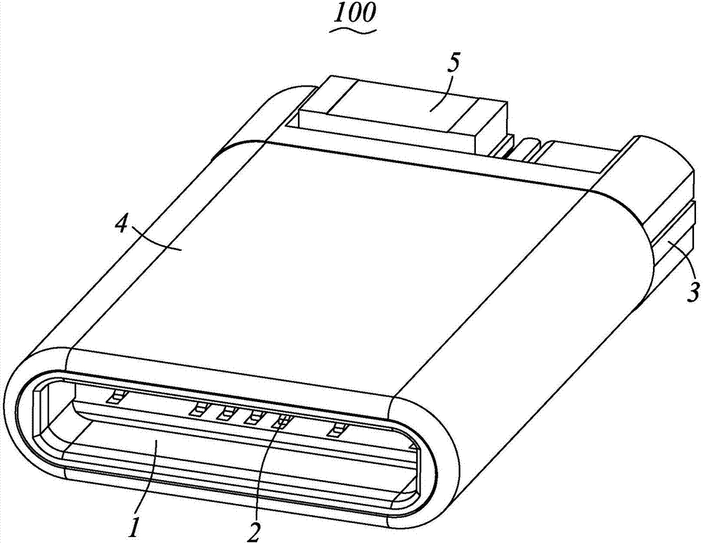
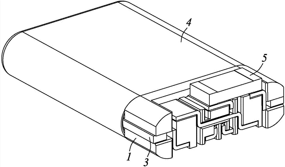
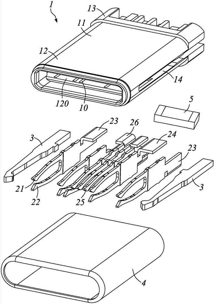
[0030] Please refer to Figure 1 to Figure 11 As shown, it is a preferred embodiment of the electrical connector 100 of the present invention. The electrical connector 100 includes an insulating body 1, a plurality of conductive terminals fixed in the insulating body 1, a locking member 3, and a cover The shielding shell 4 outside the insulating body 1 and the resistance element 5 electrically connected to the corresponding conductive terminal 2.

[0031] Please refer to Figure 1 to Figure 4 And combine Figure 7 to Figure 9 As shown, the insulating body 1 has a main body 11, a docking portion 12 disposed in front of the ma...


PUM


Abstract

The invention provides an electric connector, and the connector comprises an insulating body, a plurality of conductive terminals fixed in the insulating body, a lock catch part, and a shading housing covering the insulating body. The insulating body is provided with an accommodation space which can be used for the insertion of a butt joint socket connector, a plurality of terminal slots which are set in a front / back direction in a passing through manner, and an installation part located at the rear end of the insulating body. The terminal slots are arranged in parallel in the lateral direction of the electric connector. The conductive terminals comprise a first terminal group and a second terminal group, which are arranged in two rows in the height direction. The conductive terminals are assembly in the terminal slots from the rear to the front, and are provided with welding parts which are exposed out of the installation part and are arranged in two rows. The installation part of the insulating body is provided with a plurality of fences set in the height direction, and the fences enable the adjacent welding parts to be isolated from each other. The welding parts are respectively of a plate-shaped structure which is set horizontally, so as to achieve the electrical connection with a cable. The connector can save a built-in circuit board structure, saves the cost, and an simplify the technology.

Description

Technical field [0001] The present invention relates to the technical field of connectors, and in particular to an electrical connector that can be plugged in front and back. Background technique [0002] With the rapid development of science and technology in the electronics industry, the volume of electronic products is developing along the trend of becoming thinner and shorter. This also requires the size of electronic products to become smaller and smaller, and the connector industry is the first to bear the brunt. . [0003] As the size of the new generation of USB Type-C connectors is required to be smaller, this leads to better mechanical performance requirements and higher product design difficulties. In order to face lighter, thinner and slimmer equipment and ensure the reliability of product structure, major manufacturers have introduced corresponding structural designs. [0004] In the existing USB Type-C plug connector, the conductive terminals of the two terminal assem...

Claims


Application Information

Patent Timeline
IPC IPC(8): H01R13/02H01R13/40H01R13/627H01R13/64
CPCH01R13/02H01R13/40H01R13/648
Inventor 彭易平
Owner ALL BEST ELECTRONICS TECH CO LTD
Features
  • R&D
  • Intellectual Property
  • Life Sciences
  • Materials
  • Tech Scout
  • Unparalleled Data Quality
  • Higher Quality Content
  • 60% Fewer Hallucinations
Learn More