Phase-change switch for three-phase unbalance treatment device and phase-change method thereof

A commutation switch, three-phase technology, applied in the direction of electronic switch, multi-phase network asymmetry reduction, multi-phase network elimination/reduction of asymmetry, etc., can solve problems such as large on-state loss, easy misconduct, inrush current damage, etc. , to achieve the effect of small self-loss, no electromagnetic pollution, and reduced loss

Inactive Publication Date: 2017-08-11
CHINA EPRI SCIENCE & TECHNOLOGY CO LTD +3
View PDF3 Cites 4 Cited by
  • Summary
  • Abstract
  • Description
  • Claims
  • Application Information

AI Technical Summary

Problems solved by technology

During operation, the on-state voltage drop of the thyristor is about 1V, and the on-state loss is relatively large. It is necessary to install a radiator or a forced air cooling device to avoid thermal breakdown of the PN junction. At the same time, the thyristor is very sensitive to the voltage change rate (dv / dt). Sensitive, it is easy to be misconducted and damaged by inrush current in case of sudden voltage changes such as operating overvoltage and lightning strike

Method used


Image

  • Phase-change switch for three-phase unbalance treatment device and phase-change method thereof
  • Phase-change switch for three-phase unbalance treatment device and phase-change method thereof

Examples


Embodiment

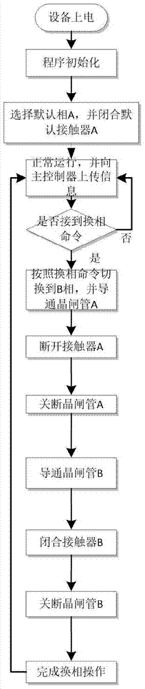
[0034] like figure 2 As shown, the present invention provides a commutation method of a commutation switch of a three-phase unbalance control device comprising the following steps:

[0035] (1) Power on the three-phase unbalance control device. After the program is initialized, select the default phase A and close the default AC contactor A;

[0036] (2) The three-phase unbalance control device is operating normally and uploading information to the main controller;

[0037] (3) Judging whether the commutation command is received, if received, switch to phase B according to the commutation command, and turn on the thyristor valve A; if not received, return to the previous step;

[0038] (4) Disconnect AC contactor A;

[0039] (5) Turn off the thyristor valve A;

[0040] (6) Turn on the thyristor valve B;

[0041] (7) Turn off the AC contactor B;

[0042] (8) Turn off the thyristor valve B to complete the commutation operation. The maximum commutation time is 10ms.

[00...


PUM


Abstract

The invention relates to a phase-change switch for a three-phase unbalance treatment device and a phase-change method thereof. The phase-change switch comprises a phase-change switch shell and a three-phase thyristor valve-AC contactor parallel structure and a trigger board encapsulated in the shell; and the thyristor valve-AC contactor parallel structure is connected with a current transformer. The phase-change method comprises the following steps: keeping the phase-change switch in a working phase, wherein the AC contactor in the working phase is closed and the thyristor is latched; the AC contactor in a non-working phase is in a break-brake state and the thyristor is latched; and when the three-phase unbalance of a power system exceeds the national standard, switching the phase-change switch to a low load phase. The technical scheme provided by the invention adopts a mode that the contactor is used in parallel with the thyristor, and combines the characteristics that the running power consumption of the contactor is small and the switching speed of the thyristor is fast, so that the phase-change switch of the three-phase unbalance treatment device has both the advantages of the AC contactor and a power electronic fling-cut switch, thus there is no power outage in the phase change process and no impact on the system at the same time.

Description

technical field [0001] The invention relates to a power electronic device and method, in particular to a phase commutation switch of a three-phase unbalance control device and a phase commutation method thereof. Background technique [0002] In the low-voltage distribution network system, there are a large number of single-phase and asymmetrical loads, and the operation of three-phase loads changes randomly. These loads will cause three-phase unbalance in the power distribution system, resulting in unbalanced three-phase voltage and current in the power supply system. Negative-sequence voltage and negative-sequence current will be generated, which will reduce the quality of power supply and affect the normal power consumption of users in severe cases. At the same time, it will increase the loss of lines and transformers, reduce the reliability of power supply, and even cause serious power failures such as large-scale power outages and neutral line blowouts. as a result of. ...

Claims


Application Information

Patent Timeline
Patent Type & Authority Applications(China)
IPC IPC(8): H03K17/725H02J3/26
CPCY02E40/50H03K17/725H02J3/26
Inventor 尹元亚刘洋洋叶卫华缪伟夏民崔椿洪葛明明袁蒙贲宝强周娴姊任思源
Owner CHINA EPRI SCIENCE & TECHNOLOGY CO LTD
Why Eureka
Try Eureka