
Optical path control system and optical module

A control system and optical path technology, applied in transmission systems, electromagnetic wave transmission systems, optics, etc., can solve the problems of the large size of the optical path control system 1, unfavorable miniaturization of optical modules, and complex assembly processes, so as to reduce the number of optical circuit devices, Simple structure and cost reduction effect

Active Publication Date: 2017-08-15
INNOLIGHT TECHNOLOGY (SUZHOU) LTD
View PDF12 Cites 5 Cited by
  • Summary
  • Abstract
  • Description
  • Claims
  • Application Information

AI Technical Summary

Problems solved by technology

In addition, due to the small aperture of the photodetector, it is difficult for the divergent light beam to be fully coupled into the photodetector, resulting in signal loss
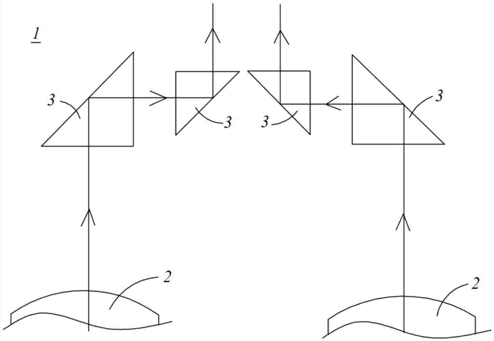
[0003] like figure 1 As shown, in the traditional multi-channel parallel optical path system, the optical path spacing is adjusted by the optical path control system 1, and the method of changing the optical path spacing and focusing method needs to use multiple objective lenses 2 and multiple prisms 3, and the distance between the objective lens 2 and the prism 3 The distance between them and the distance between multiple prisms 3 are relatively large, resulting in the bulky size of the entire optical path control system 1, which is not conducive to the miniaturization of optical modules; Precise control is required, and the assembly process is more complicated

Method used


Image

  • Optical path control system and optical module
  • Optical path control system and optical module
  • Optical path control system and optical module

Examples


Embodiment Construction

[0020] The application will be described in detail below in conjunction with specific implementations shown in the accompanying drawings. However, these implementations do not limit the present application, and any structural, method, or functional changes made by those skilled in the art based on these implementations are included in the protection scope of the present application.

[0021] In each drawing of the present application, some dimensions of structures or parts are exaggerated relative to other structures or parts for convenience of illustration, and therefore, are only used to illustrate the basic structure of the subject matter of the present application.

[0022] In addition, terms used herein such as "upper", "above", "under", "below", etc. to express relative positions in space are for convenience of description to describe a unit or feature as shown in the drawings relative to A relationship to another cell or feature. The terms of spatial relative position ...


PUM


Abstract

The present invention discloses an optical path control system and an optical module. The system comprises a focusing lens and an optical path acting assembly; the focusing lens is used for converging light beams passing through the focusing lens; the optical path acting assembly is used for controlling the transmission direction of the light beams; and when a plurality of incident light beams pass through the optical path acting assembly and the focusing lens sequentially, the optical path acting assembly converges the plurality of incident light beams, and the focusing lens converges each incident light beam into a light spot. According to the optical path control system and the optical module of the present invention, the intervals of the light beams can be adjusted through the functions of the optical path acting assembly and the focusing lens, and therefore, the structure of the optical path control system is simple, the number of optical path devices is reduced, the size of the whole optical path control system is greatly reduced, and thereby, the size of the whole optical module can be reduced; the relative positions of the focusing lens and the optical path acting assembly can be fixed easily, and therefore, the relative accuracy of focusing positions is improved; and the optical path acting assembly can be designed independently to realize independent control on the light beams, and the transmission direction and focusing point of each light beam can be independently controlled, and therefore, the degree of adjustment freedom is high.

Description

technical field [0001] The present application relates to the technical field of manufacturing optical communication components, in particular to an optical path control system and an optical module. Background technique [0002] In optical communication, due to the difference in the channel spacing of the optical communication devices connected to each other, it is often necessary to adjust the optical path spacing to an appropriate range before performing coupling transmission. In addition, due to the small aperture of the photodetector, it is difficult to fully couple the divergent light beams into the photodetector, resulting in signal loss. [0003] Such as figure 1 As shown, in the traditional multi-channel parallel optical path system, the optical path spacing is adjusted by the optical path control system 1, and the method of changing the optical path spacing and focusing method needs to use multiple objective lenses 2 and multiple prisms 3, and the distance between...

Claims


Application Information

Patent Timeline
Patent Type & Authority Applications(China)
IPC IPC(8): G02B26/08G02B6/42
CPCG02B6/4286G02B26/0875G02B6/4246H04B10/11H04B10/40G02B19/0014G02B6/4214G02B27/1006H04B10/25891G02B6/2938G02B6/4206
Inventor 于登群孙雨舟陈龙王冬寒李伟龙
Owner INNOLIGHT TECHNOLOGY (SUZHOU) LTD
Learn More