
Power Systems

A technology of power system and electric energy, applied in the field of power system, can solve the problems of complicated converter control and so on

Active Publication Date: 2019-12-31
DANFOSS MOBILE ELECTRIFICATION OY
View PDF7 Cites 0 Cited by
  • Summary
  • Abstract
  • Description
  • Claims
  • Application Information

AI Technical Summary

Problems solved by technology

However, this solution complicates the control of the converter

Method used


Image

  • Power Systems
  • Power Systems

Examples


Embodiment Construction

[0024] The specific examples provided in the description given below should not be construed as limiting the scope and / or applicability of the appended claims. The lists and groups of examples provided in the description given below are not exhaustive unless expressly stated otherwise.

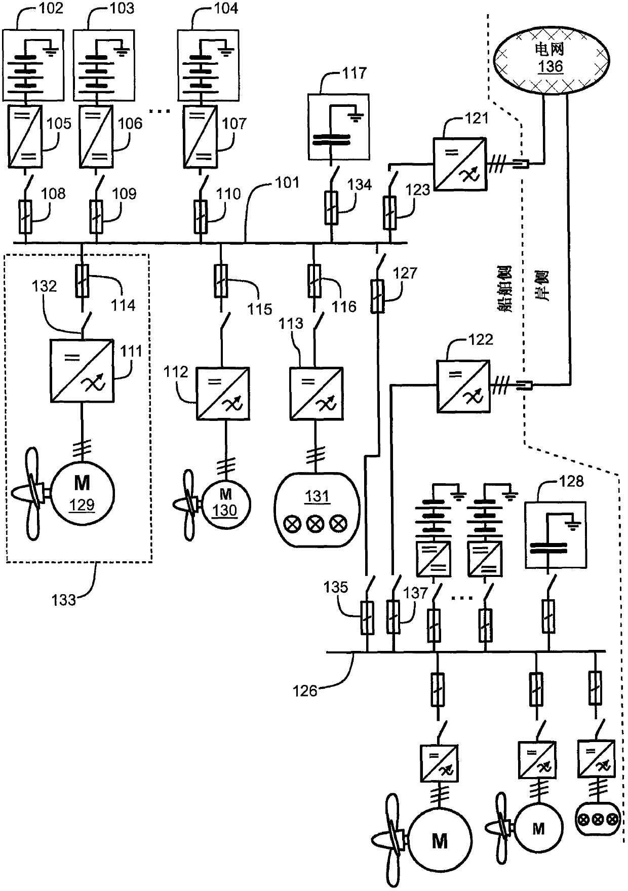
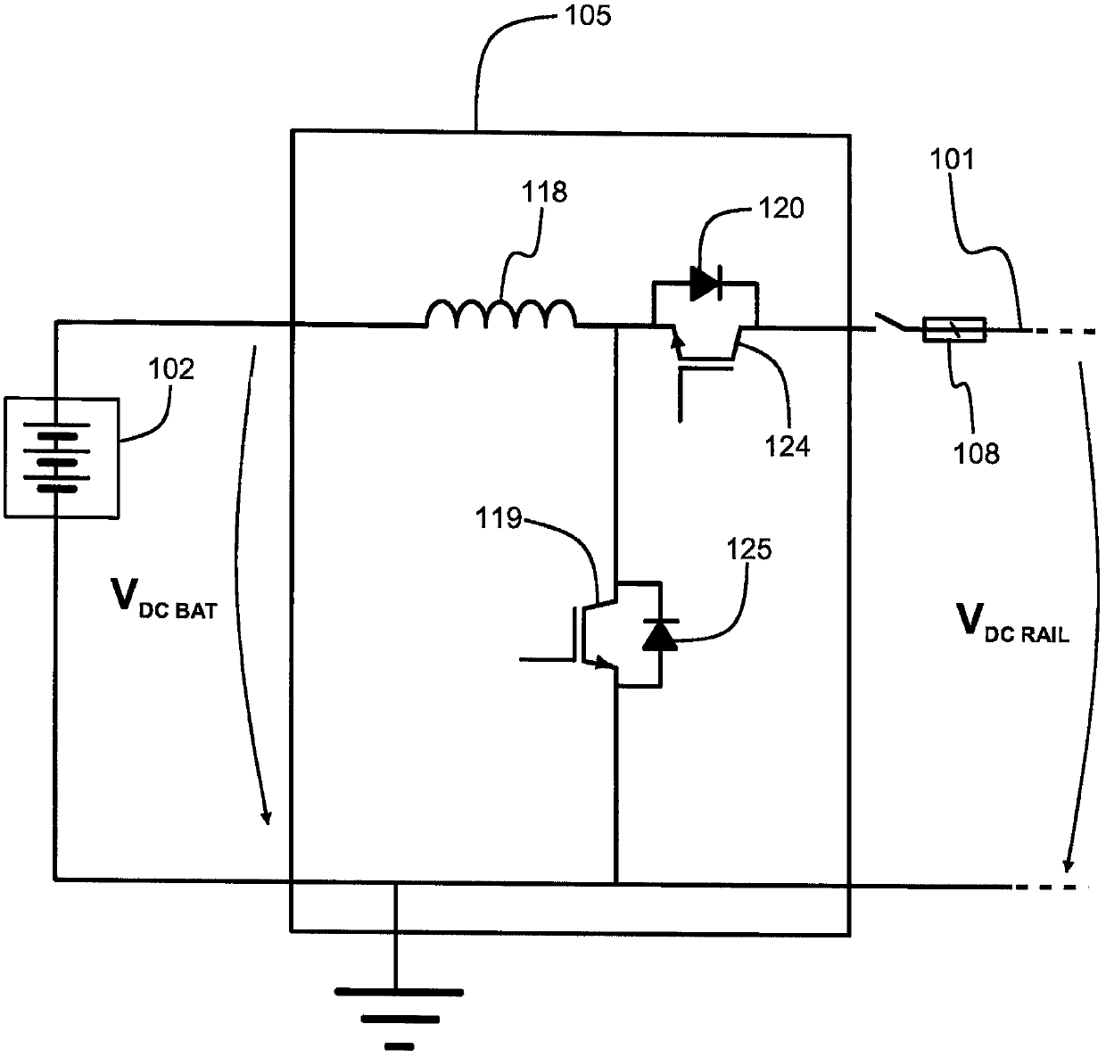
[0025] Figure 1a A schematic diagram of a power system according to an exemplary and non-limiting embodiment of the invention is shown. In this exemplary case, the electrical system is that of a ship. The power system includes a DC voltage rail 101, a battery element, and a power converter for transferring electrical energy from the battery element to the DC voltage rail. exist Figure 1a In , reference numerals 102 , 103 and 104 represent three of the battery elements, and reference numerals 105 , 106 and 107 represent three of the power converters. The power system includes a load converter for converting the DC voltage of the DC voltage rail 101 into a voltage suitable for the load of th...


PUM


Abstract

A power system comprising a DC voltage rail (101), a battery element (102-104) connected to said DC voltage rail using a power converter (105-107), and a DC voltage for converting said DC voltage rail a load converter (111-113) for a voltage suitable for a load of the power system, wherein the power converter and the load converter are connected to the the DC voltage rail. The power system further includes a capacitor system (117) connected to a DC voltage rail and capable of responding to causing a voltage drop at an electrical node connected to the DC voltage rail via the overcurrent protector fault, and supply the fault current used to switch the overcurrent protector to non-conductive state.

Description

technical field [0001] The present disclosure relates to an electrical system, which may be, for example but not necessarily, a marine electrical system. Background technique [0002] In many cases, a power system includes a DC voltage rail, one or more battery elements for powering the DC voltage rail, and one or more loads for converting the DC voltage from the DC voltage rail to a power system voltage to one or more load converters. The electrical system may eg be a ship's electrical system, in which case the loads of the electrical system may include one or more propulsion motors, the ship's AC voltage network, and other loads such as one or more bow propulsion motors. The electric motor is advantageously an alternating current "AC" motor and the corresponding load converter is an inverter for converting the DC voltage of the DC voltage rail into an AC voltage suitable for the AC motor. [0003] In many cases it is advantageous that the DC voltage of the DC voltage rai...

Claims


Application Information

Patent Timeline
Patent Type & Authority Patents(China)
IPC IPC(8): H02H3/02H02H7/26H02H9/02
CPCH02H3/025H02H7/268H02H9/02B60L2200/32B60L2210/40B60L50/40B60L50/51H02H1/06H02H3/087H02H3/20H02H7/12Y02T10/70Y02T10/72B63J2003/002H02J1/10H02H7/1213H02M3/158H02P27/06
Inventor 泰罗·耶尔韦莱宁基莫·劳玛
Owner DANFOSS MOBILE ELECTRIFICATION OY
Learn More