Motor with brake in rear end cap

A technology of rear end cover and brake, which is applied in the direction of controlling mechanical energy, electrical components, electromechanical devices, etc. It can solve the problems of large volume ratio, influence of the motor body, and powder generated by the friction plate, so as to meet the requirements of lightweight and reduce the weight of the motor , Compact structure and simple effect

Pending Publication Date: 2017-08-15
NANJING ESTUN AUTOMATION CO LTD
View PDF5 Cites 2 Cited by
  • Summary
  • Abstract
  • Description
  • Claims
  • Application Information

AI Technical Summary

Problems solved by technology

[0002] With the wide application of automation and semi-automation equipment in industrial industries, especially in industries such as robots, special servo equipment, and conventional servo equipment, the volume of existing servo motors with brakes is relatively large, and the motors are easily affected by motor brake dust. And the back-end structure is not convenient for real-time adjustment and maintenance
[0003] Most of the existing motors with brakes are installed with the brakes reversed, and the brakes are fixed on the front end of the rear end cover and placed inside the casing. During the braking process of the brakes, the friction plates will produce powder, which will damage the motor. At the same time, installing the brake inside the casing will also have a certain impact on product assembly and subsequent product disassembly and maintenance.

Method used


Image

  • Motor with brake in rear end cap
  • Motor with brake in rear end cap
  • Motor with brake in rear end cap

Examples


Embodiment

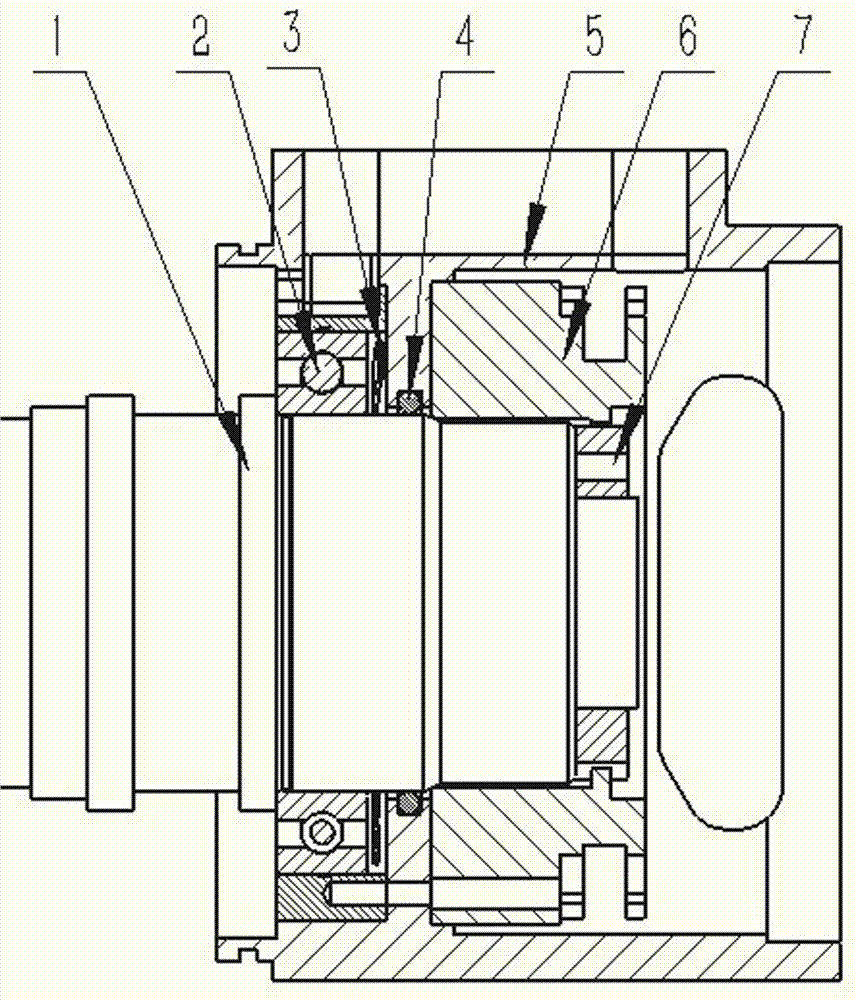
[0017] A motor with a brake in the rear end cover, the structure of the rear end of the shaft is as follows figure 1 shown. The rotating shaft 1 is assembled with the bearing 2 to ensure that the rotating shaft 1 and the inner ring of the bearing 2 are tightly fitted. At the same time, the brake rotor 7 is assembled to the rear end of the rotating shaft 1, such as Figure 4 shown.

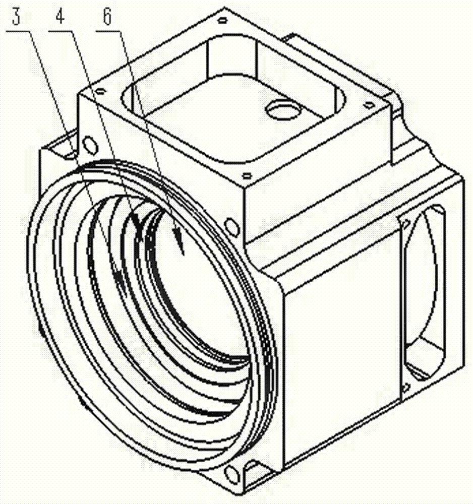
[0018] Such as figure 1 , 2 , As shown in 3, the rear end cover 5 is divided into a bearing chamber and a brake chamber. There is a rotating shaft hole between the bearing chamber and the brake chamber, and a sealing ring groove is formed on the inner circumference of the rotating shaft hole, and a sealing ring 4 is arranged in the sealing ring groove. The rear end of the rotating shaft 1 passes through the rotating shaft hole and is inserted into the brake chamber of the rear end cover, and the sealing ring 4 seals between the rotating shaft 1 and the rotating shaft hole. The rear end cover ...


PUM


Abstract

The invention discloses a motor with a brake in a rear end cap. The rear end cap is divided into a bearing chamber and a brake chamber, and a rotating shaft hole is formed between the bearing chamber and the brake chamber. The rear end portion of a rotating shaft penetrates the rotating shaft hole and is then placed in the brake chamber of the rear end cap, and space between the rotating shaft and the rotating shaft hole is sealed by a sealing ring. A bearing is arranged in the bearing chamber of the rear end cap, and an elastic component is assembled in a compressed way between the bearing and the rotating shaft hole. The brake is placed in the brake chamber of the rear end cap and installed in the rear end portion of the rotating shaft. The rear end cap is provided with an operation window in the side of the brake chamber. According to the invention, the rear end cap of the motor includes the brake, space between the brake and the bearing chamber is sealed, and influence of dust on a motor body is reduced. The operation window is reserved in the rear end cap, so that requirements for operating and adjusting the rear end of the motor are satisfied in real time in the motor using process. The structure is compact and simple, the occupation space is small, the motor weight is reduced, and the motor is light and convenient to maintain.

Description

technical field [0001] The invention relates to a motor with a brake, in particular to a motor with a brake in the rear end cover. Background technique [0002] With the wide application of automation and semi-automation equipment in industrial industries, especially in industries such as robots, special servo equipment, and conventional servo equipment, the volume of existing servo motors with brakes is relatively large, and the motors are easily affected by motor brake dust. And the back-end structure is not convenient for real-time adjustment and maintenance. [0003] Most of the existing motors with brakes are installed with the brakes reversed, and the brakes are fixed on the front end of the rear end cover and placed inside the casing. During the braking process of the brakes, the friction plates will produce powder, which will damage the motor. At the same time, installing the brake inside the casing will also have a certain impact on product assembly, subsequent pro...

Claims


Application Information

Patent Timeline
Patent Type & Authority Applications(China)
IPC IPC(8): H02K7/10H02K5/16H02K5/10
CPCH02K5/10H02K5/16H02K7/10
Inventor 郝涛涛张建孙园园仲丽丽钱巍吴波
Owner NANJING ESTUN AUTOMATION CO LTD
Why Eureka
Try Eureka