Optical power monitoring component and optical module

A technology of optical power monitoring and components, which is applied in the field of optical communication, can solve the problems of complex structure, poor stability of optical power monitoring components, high requirements for optical path accuracy, etc., and achieve the effect of high installation accuracy

Inactive Publication Date: 2017-08-15
INNOLIGHT TECHNOLOGY (SUZHOU) LTD
View PDF3 Cites 0 Cited by
  • Summary
  • Abstract
  • Description
  • Claims
  • Application Information

AI Technical Summary

Problems solved by technology

However, the optical power monitoring component composed of optical beam-splitting lenses has a complex structure, requires high precision of the optical path, and the stability of the optical power monitoring component is poor.

Method used


Image

  • Optical power monitoring component and optical module
  • Optical power monitoring component and optical module
  • Optical power monitoring component and optical module

Examples


Embodiment Construction

[0030] The application will be described in detail below in conjunction with specific implementations shown in the accompanying drawings. However, these implementations do not limit the present application, and any structural, method, or functional changes made by those skilled in the art based on these implementations are included in the protection scope of the present application.

[0031] In each drawing of the present application, some dimensions of structures or parts are exaggerated relative to other structures or parts for the convenience of illustration, and therefore, are only used to illustrate the basic structure of the subject matter of the present application.

[0032] The terms used herein to denote relative spatial positions such as "upper", "above", "under", "under", etc. are for convenience of description to describe the relative position of one element or feature relative to another as shown in the drawings. Relationships of units or features. The terms of s...


PUM


Abstract

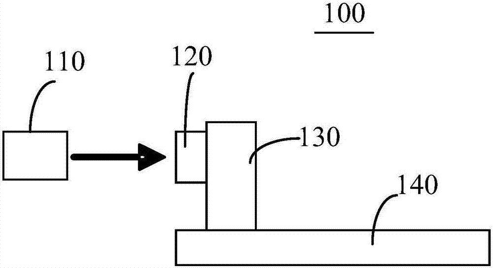
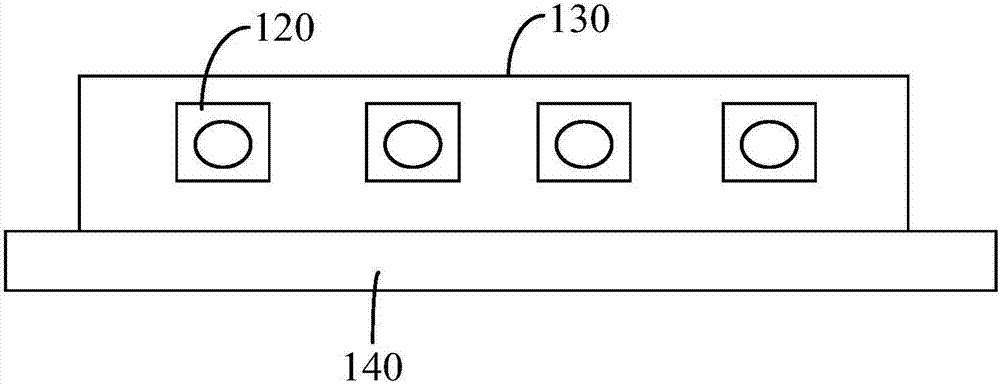
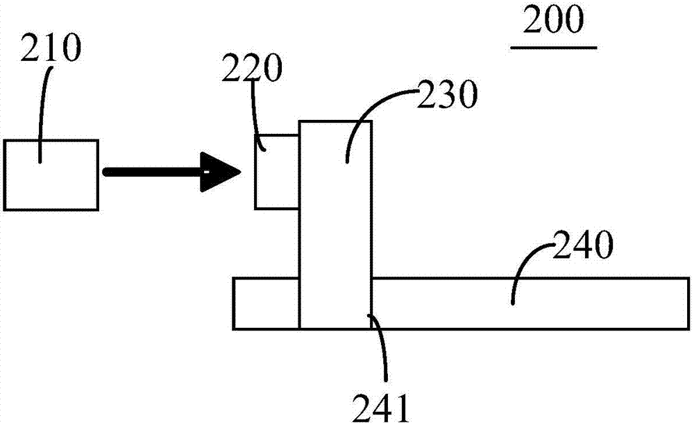
The application discloses an optical power monitoring component and an optical module. The optical power monitoring component comprises lasers, photoelectric detectors, a fixing device and a circuit board, wherein the lasers at least output forward light for transmitting optical signals and backward light for monitoring optical power; the photoelectric detectors are arranged in one-to-one correspondence with the lasers and are used for receiving the backward light transmitted by the lasers and converting the backward light into electric signals; the photoelectric detectors are fixedly arranged on the fixing device; the fixing device is fixedly arranged on the circuit board; and the circuit board, the fixing device and the photoelectric detectors are electrically connected, and the circuit board receives the electric signals of the photoelectric detectors. According to the optical power monitoring component and the optical module disclosed by the application, the optical power monitoring component monitors the optical power of the lasers through the backward light emitted by the lasers, and thus a simple structure and relatively high component stability can be achieved; and the integrated monitoring of multiple paths of lasers can be achieved through a substrate or multiple contact pins, and the photoelectric detectors are high in installation accuracy.

Description

technical field [0001] The application belongs to the technical field of optical communication, and in particular relates to an optical power monitoring component and an optical module. Background technique [0002] The optical module is composed of optoelectronic devices, functional circuits and optical ports. Among them, optoelectronic devices include two parts: emission and reception. To put it simply, the main function of the optical module is to realize photoelectric conversion. At the sending end, the electrical signal is converted into an optical signal. After transmission through the optical fiber, the optical signal is converted into an electrical signal at the receiving end, thereby realizing the transmission of information. [0003] In the optical module, it is usually necessary to adjust the optical power of the laser according to specific conditions, which requires monitoring the optical power of the laser first. In the optical power monitoring component of th...

Claims


Application Information

Patent Timeline
Patent Type & Authority Applications(China)
IPC IPC(8): H04B10/07
CPCH04B10/07
Inventor 孙雨舟陈龙王冬寒李伟龙于登群
Owner INNOLIGHT TECHNOLOGY (SUZHOU) LTD
Why Eureka
Try Eureka