
Grinding machine with single-sided chamfering grinding function

A grinding machine and chamfering technology, which is applied to machine tools suitable for grinding workpiece planes, machine tools suitable for grinding workpiece edges, grinding frames, etc., can solve the problems affecting construction progress, time-consuming and laborious, and poor grinding effect. problems, to reduce labor intensity, prevent environmental pollution, and improve work efficiency.

Active Publication Date: 2017-08-18
海通智能装备(江苏)有限公司
View PDF5 Cites 4 Cited by
  • Summary
  • Abstract
  • Description
  • Claims
  • Application Information

AI Technical Summary

Problems solved by technology

Usually, construction workers use a hand-held grinder for grinding. The labor intensity of the workers is high, time-consuming and labor-intensive, the surface after grinding is uneven, the grinding effect is poor, and the grinding accuracy is poor. During the construction process, it is usually necessary to perform unilateral chamfering on some stones. Edge work, usually after the grinding machine is finished, the polished stone is chamfered and trimmed by the chamfering and trimming machine, but the traditional stone processing and grinding device has a single function, and the chamfering and trimming cannot be performed in time after the grinding is completed. It is often necessary to re-move the stone to the chamfering and trimming machine for trimming. The steps are cumbersome and the workload is large, which affects the construction progress and cannot meet the existing needs.

Method used


Image

  • Grinding machine with single-sided chamfering grinding function
  • Grinding machine with single-sided chamfering grinding function
  • Grinding machine with single-sided chamfering grinding function

Examples


Embodiment 1

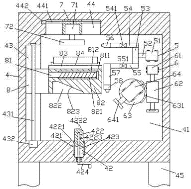
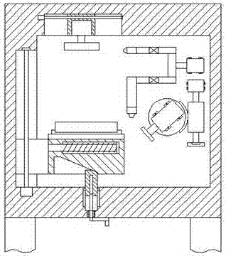
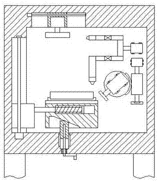
[0035] When automatic grinding and automatic chamfering and edge trimming are required, the stone is installed in the fixture 84, and then the first threaded rod 431 is driven by the first motor 432 to reverse, so that the first threaded rod 431 drives the first slider 8 and the second The grinding table 82 on the right side of the slider 8 moves upwards along the first chute 43 until the top surface of the stone abuts against the first grinding wheel 72. At this time, the first control valve 541 is controlled to open and the second control valve 551 is closed. , the second motor 442 drives the second threaded rod 441 to rotate left and right, so as to realize the left and right motion grinding work. At this time, the third threaded rod 423 is driven to reverse by rotating the handle 424, so that the third threaded rod 423 drives the pressing slider 422 Move upward until the convex slider 4221 moves to the topmost position of the third chute 421. At this time, the pressing slid...

Embodiment 2

[0037] When it is only necessary to complete the grinding work on the top of the stone, the stone is installed in the fixture 84, and then the first motor 432 drives the first threaded rod 431 to reverse, so that the first threaded rod 431 drives the first slider 8 and the first slider 8. The grinding table 82 on the right side moves upward along the first chute 43 until the top end surface of the stone abuts against the first grinding wheel 72. At this time, the first control valve 541 is controlled to open and the second control valve 551 is closed. The second motor 442 drives the second threaded rod 441 to rotate left and right. After the grinding is completed, the first motor 432 drives the first threaded rod 431 to rotate, so that the first slider 8 is located at the bottom position of the first chute 43, and finally the stone is taken out. That's it.

Embodiment 3

[0039] When only chamfering and edge trimming work is required, the stone is installed in the fixture 84, and the third threaded rod 423 is reversed by turning the handle 424, so that the third threaded rod 423 drives the top pressure slider 422 to move upwards, making the top pressure slide The block 422 gradually extends into the fourth chute 822 until the second slope 4222 abuts against the right section of the first slope 823. At this time, the first control valve 541 is controlled to be closed and the second control valve 551 is opened. 424 drives the third threaded rod 423 to reverse, so that the third threaded rod 423 drives the pressing slider 422 to move upwards. At this time, the second inclined surface 4222 is press-fitted with the first inclined surface 823, so that the grinding table 82 overcomes the effect of the spring 812 The power gradually moves to the right until the top end surface of the top pressing slide block 422 abuts against the inner top wall of the f...


PUM


Abstract

The invention discloses a grinding machine with a single-sided chamfering grinding function. The grinding machine comprises a machine body with supporting posts at two sides, wherein a grinding cavity is arranged in the machine body; a first slide slot is formed in the inner wall at the left side of the grinding cavity; a second slide slot is formed in a position, close to one side of the first slide slot, on the top wall in the grinding cavity; a first slide cavity is arranged in the bottom wall in the grinding cavity; a first threaded rod is arranged in the first slide slot; a first slide block is connected on the first threaded rod in a screw-thread fit mode; a grinding table is arranged at the right side of the first slide block; a fourth slide slot is formed in the bottom end surface of the grinding table; a second slide cavity is arranged in the grinding table; a limiting slide block is connected in the second slide cavity in a sliding fit mode; and a guide slide rod which extends towards the left side is fixedly arranged at the left side end of the limiting slide block. The grinding machine is simple in structure, is reasonable in design, can automatically complete grinding and chamfering-trimming work, can realize regulation on dust-absorbing as well as a chambering-trimming angle, is convenient to operate, saves time and labor, improves working efficiency and reduces labor intensity.

Description

technical field [0001] The invention relates to the technical field of building construction equipment, and relates to a grinding machine with the function of single-side chamfering and grinding. Background technique [0002] Stone is a high-grade building decoration material, which can be seen everywhere and has a wide range of applications. Regardless of natural stone or synthetic stone, the surface is generally rough and needs to be polished to achieve a radiant effect. Usually, construction workers use a hand-held grinder for grinding. The labor intensity of the workers is high, time-consuming and labor-intensive, the surface after grinding is uneven, the grinding effect is poor, and the grinding accuracy is poor. During the construction process, it is usually necessary to perform unilateral chamfering on some stones. Edge work, usually after the grinding machine is finished, the polished stone is chamfered and trimmed by the chamfering and trimming machine, but the tra...

Claims


Application Information

Patent Timeline
IPC IPC(8): B24B27/00B24B7/22B24B9/06B24B41/06B24B41/02B24B41/00B24B47/04B24B47/12B24B55/06
CPCB24B7/224B24B9/06B24B27/0076B24B41/007B24B41/02B24B41/068B24B47/04B24B47/12B24B55/06
Inventor 余霞
Owner 海通智能装备(江苏)有限公司
Learn More