Fast airship capsule inflating system and method

An inflation system and capsule technology, applied in the field of aircraft, can solve problems such as increased inflation costs and pipeline rupture, and achieve the effects of protecting equipment safety and reducing manufacturing costs

Inactive Publication Date: 2017-08-18
杭州东沣科技有限公司
View PDF6 Cites 3 Cited by
  • Summary
  • Abstract
  • Description
  • Claims
  • Application Information

AI Technical Summary

Problems solved by technology

[0003] In addition, the existing inflatable pipeline is made of flexible materials. When the gas flows in the inflatable pipeline, if the pipeline is folded and twisted, it is easy to cause the pipeline to rupture due to a sharp increase in gas pressure; in order to reduce the pressure of the airflow, It is necessary to design a set of shunt pipelines, which are externally connected to the outside of the capsule, which increases the cost of inflation

Method used


Image

  • Fast airship capsule inflating system and method
  • Fast airship capsule inflating system and method

Examples


Embodiment 1

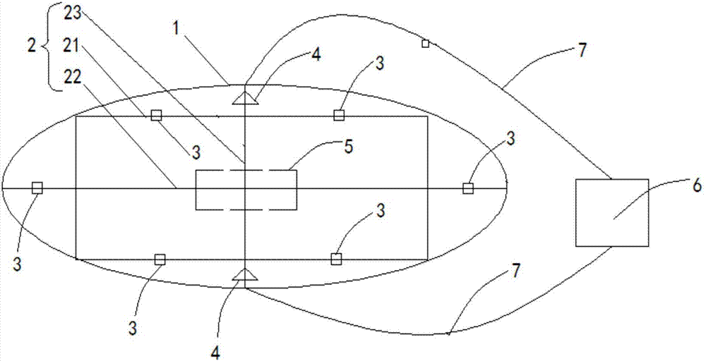
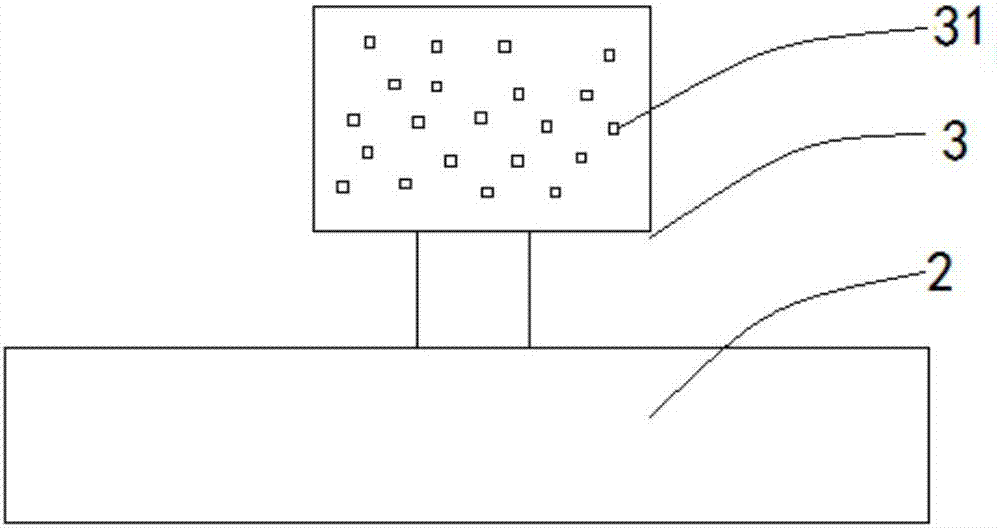
[0029] Such as Figure 1-Figure 2 As shown, a rapid inflation system for an airship capsule includes a capsule 1, a support frame 2, a diffusion device 3 for shunting and decompression, a differential pressure sensor, an inflation joint 4 and a control system 5; the capsule 1 is ellipsoidal, The support frame 2 is made by connecting hollow support rods, and is arranged horizontally in the capsule body 1. The diffusion device 3 is installed on the support frame 2. One end of the diffusion device 3 communicates with the hollow support rod of the support frame 2, and the other end communicates with the capsule body. The inside of the body 1 is connected, the differential pressure sensor is arranged in the capsule body 1 , the inflation joint 4 is installed on both sides of the short axis direction of the capsule body 1 , and the control system 5 is installed in the middle of the support frame 2 . The inflation system is inflated by an external high-pressure gas source 6 through a...

Embodiment 2

[0036] A method for rapidly inflating an airship capsule, comprising the following steps:

[0037] Step 1, using the inflation pipeline 7 to connect the high-pressure gas source 6 to the intake end of the inflation connector 4, and connect the high-pressure gas source 6 to the control system 5;

[0038] Step 2, the control system 5 issues an instruction to start inflation, starts the high-pressure air source 6, and inflates the bladder 1;

[0039] Step 3, when the differential pressure sensor detects that the differential pressure reaches the differential pressure threshold, the control system 5 issues an instruction to stop inflation, turns off the high-pressure gas source 6, and disconnects the inflation pipeline 7 from the gas inlet of the inflation joint 4.

[0040] The pressure difference value is the difference between the gas pressure inside the capsule body 1 and the atmospheric pressure outside the capsule body 1 .

[0041] Step 2 also includes: after starting the hi...


PUM


Abstract

The invention relates to a fast airship capsule inflating system and a fast airship capsule inflating method. The fast airship capsule inflating system comprises a supporting framework, a capsule, diffusing devices for shunting and decompressing gas, a pressure difference sensor, inflating connectors and a control system, wherein the capsule is an ellipsoid; the supporting framework is formed by connecting hollow supporting rods and is horizontally arranged inside the capsule; the diffusing devices are mounted on the supporting framework; the pressure difference sensor is arranged inside the capsule; the inflating connectors are mounted on the two sides of the minor axis of the capsule; the control system is mounted at the middle part of the supporting framework, is electrically connected with the pressure difference sensor and a high-pressure gas source, and is used for controlling opening and closure of the high-pressure gas source. In the capsule, the hollow supporting framework and the diffusing devices are used for shunting and decompressing the gas, so that conversion of high-pressure gas into a gas flow with relatively low pressure and a stable flow speed is achieved, and an external shunting and decompressing device is replaced and the manufacturing cost is reduced; change of the internal pressure of the capsule can be detected in real time, so that the equipment safety is protected.

Description

technical field [0001] The invention relates to the technical field of aircraft, in particular to a rapid inflation system and method for an airship capsule. Background technique [0002] When inflating traditional airships, steel cylinders or high-pressure helium vehicles are mainly used to introduce helium into the inflation pipeline, and then enter the bladder from the inflation pipeline. Since the airship capsule is made of flexible materials, it is not possible to directly fill a large amount of high-pressure gas into the capsule. It is necessary to be equipped with a corresponding decompression shunt to convert the high-pressure gas into a relatively low-pressure, stable flow rate. [0003] In addition, the existing inflatable pipeline is made of flexible materials. When the gas flows in the inflatable pipeline, if the pipeline is folded and twisted, it is easy to cause the pipeline to rupture due to a sharp increase in gas pressure; in order to reduce the pressure of ...

Claims


Application Information

Patent Timeline
Patent Type & Authority Applications(China)
IPC IPC(8): B64B1/58B64B1/62
CPCB64B1/58B64B1/62
Inventor 李帜程凯
Owner 杭州东沣科技有限公司
Why Eureka
Try Eureka