Connecting structure suitable for tunnel segment longitudinal seam

A technology for connecting structures and tunnel segments, which is applied in the field of connecting structures of longitudinal joints of tunnel segments, can solve problems such as increased concrete compressive stress σ, weakened segment structure, and large local stress, so as to reduce weakening and improve compressive strength Good performance and overall rigidity

Pending Publication Date: 2017-08-18
CHINA RAILWAY SIYUAN SURVEY & DESIGN GRP
View PDF9 Cites 10 Cited by
  • Summary
  • Abstract
  • Description
  • Claims
  • Application Information

AI Technical Summary

Problems solved by technology

In general, the bolts can meet the requirements of the project, but in soft ground or when the deformation of the lining ring is large, there are the following problems: 1) When the deformation of the lining ring is large, the joint of the segment under the action of the bending moment M When the gap opening θ increases, the force F of the bolts will increase, which will lead to an increase in the compressive stress σ of the concrete. When this trend continues to increase, the concrete stress σ in the compression zone may exceed the compressive strength of the concrete material, resulting in the Sheet 1 is broken (eg figure 2 shown); 2) The bolt connection method is adopted, for example, if the circumferential bolt 10 and the longitudinal bolt 11 are set, it is necessary to set the hand hole (that is, the hole of the construction bolt), the existence of the hand hole will weaken the segment structure, and the hand hole Located near the joint, especially at the corner of the segment near the connecting bolts of the circular joint and the longitudinal joint, the weakening ef

Method used


Image

  • Connecting structure suitable for tunnel segment longitudinal seam
  • Connecting structure suitable for tunnel segment longitudinal seam
  • Connecting structure suitable for tunnel segment longitudinal seam

Examples


Embodiment Construction

[0028] In order to make the object, technical solution and advantages of the present invention clearer, the present invention will be further described in detail below in conjunction with the accompanying drawings and embodiments. It should be understood that the specific embodiments described here are only used to explain the present invention, not to limit the present invention. In addition, the technical features involved in the various embodiments of the present invention described below can be combined with each other as long as they do not constitute a conflict with each other.

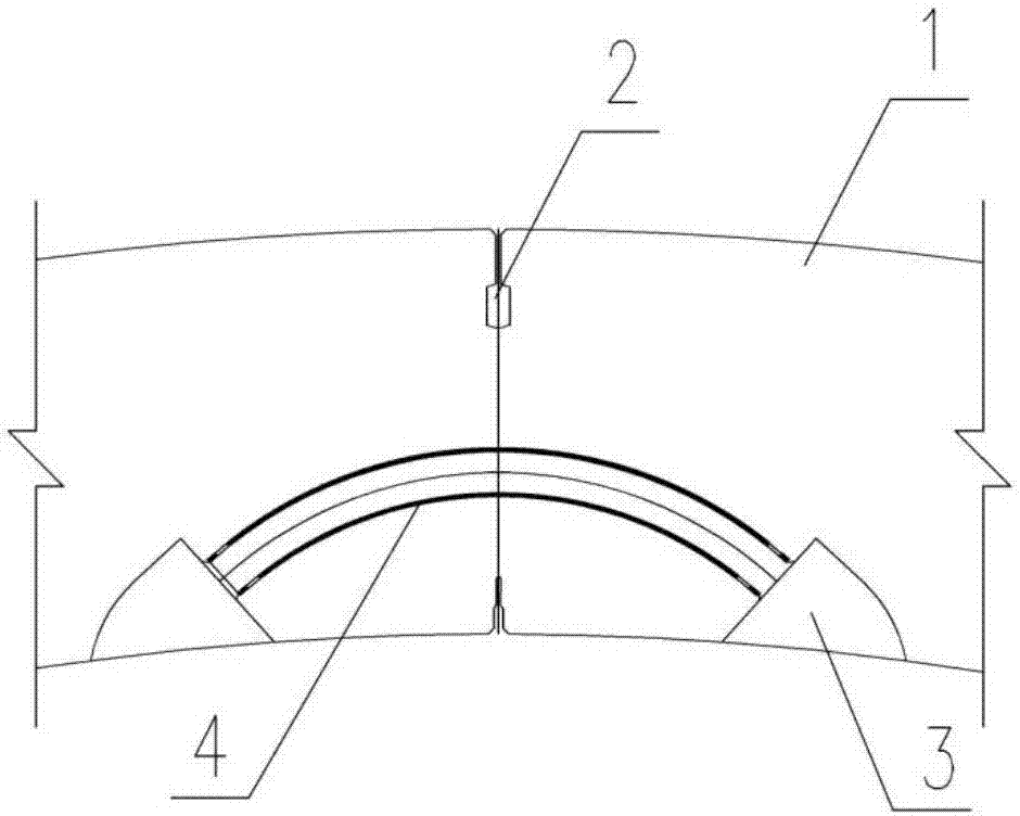
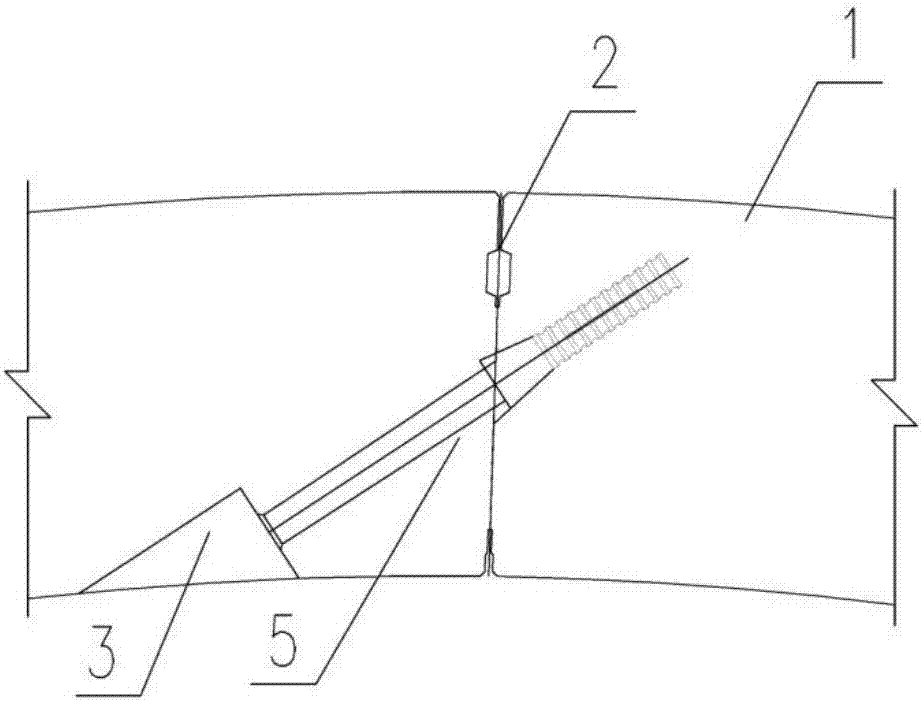
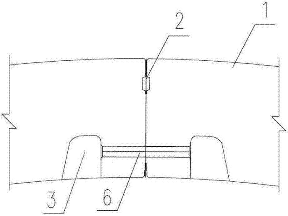
[0029] Such as Figure 4 As shown, the embodiment of the present invention provides a connection structure suitable for the longitudinal seam of the tunnel segment, the longitudinal seam is formed by two segments to be assembled (the first segment 1 and the second segment 1'), such as Figure 4 with 7 As shown, the longitudinal seam 2 is located between the first segment 1 and the second segme...


PUM


Abstract

The invention discloses a connecting structure suitable for a tunnel segment longitudinal seam. The connecting structure comprises a connecting tenon component and a mortise component, wherein the connecting tenon component is embedded in a to-be-assembled first segment, and the mortise is embedded in a to-be-assembled second segment; and the longitudinal seam is formed between the to-be-assembled first segment and the to-be-assembled second segment, wherein the distributed direction of the longitudinal seam is the same as the tunneling direction of a tunnel, the to-be-assembled first segment and the to-be-assembled second segment are tightly locked through the interlocking effect between the connecting tenon component in the to-be-assembled first segment and the mortise component in the to-be-assembled second segment, and connection of the first segment and the second segment is achieved. According to the connecting structure suitable for the tunnel segment longitudinal seam, hand holes of seam bolts can be reduced simultaneously under the condition that the rigidity of the seam is ensured, concrete force at the seam position is improved effectively, and the risk of damage of concrete at the seam position due to local compression is lowered.

Description

technical field [0001] The invention belongs to the field of tunnel segment connection structures, and more particularly relates to a connection structure suitable for longitudinal seams of tunnel segments. Background technique [0002] At present, the circumferential and longitudinal joints of the shield tunnel segments in the project are generally connected by assembling first and then installing bolts. According to different types of bolts, it can be divided into bent bolts 4, oblique bolts 5, and short straight bolts 6 (as shown in Figure 1). , in the case of large eccentric compression, the combined action of bending moment and axial force will make the segment joints open. Taking the structure under negative bending moment as an example, the open bolts on the outside of the segment joint are under tension, and the concrete surface inside the joint is under compression, and the joint is in a stable state. In general, the bolts can meet the requirements of the project,...

Claims


Application Information

Patent Timeline
IPC IPC(8): E21D11/08
CPCE21D11/083
Inventor 邓朝辉肖明清王均勇刘浩
Owner CHINA RAILWAY SIYUAN SURVEY & DESIGN GRP
Why Eureka
Try Eureka