Subway-wind-power regulating and controlling system

A control system and subway technology, applied in wind turbines, wind turbine combinations, wind turbines storing gravitational potential energy, etc., can solve the problems of low use efficiency of power generation equipment, offset ventilation effect, and high initial investment, and achieve high equipment utilization. The effect of reducing braking energy consumption and low initial investment

Active Publication Date: 2017-08-18
NANJING KULANG ELECTRONICS
View PDF10 Cites 9 Cited by
  • Summary
  • Abstract
  • Description
  • Claims
  • Application Information

AI Technical Summary

Problems solved by technology

[0007] 2. When subway piston air is used for ventilation, the direction of the piston air generated when the subway train enters and exits the station is opposite. If it is not controlled, the ventilation effects will cancel each other out;
[0008] 3. When the subway wind power is used for wind power generation, only a small part of the wind power can be used at any fixed position, so the decentralized collection mode is adopted, the use efficiency of power generation equipment is low, and the initial investment is high;

Method used


Image

  • Subway-wind-power regulating and controlling system
  • Subway-wind-power regulating and controlling system
  • Subway-wind-power regulating and controlling system

Examples


Embodiment 1

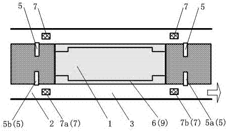
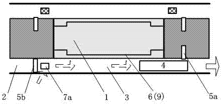
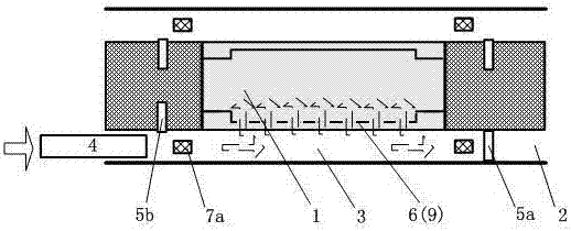
[0046] The following is attached Figure 1-5 The structure and operating conditions of the subway wind control system are introduced in detail.

[0047] In this embodiment, a piston air shaft 7 and a ventilation duct system 9 are included. The ventilation duct system 9 is used to connect the station track area 3 and the platform / station hall area 1, so as to realize the connection between the station track area 3 and the platform / station hall area 1. air exchange (attached Figure 1-5 The ventilation duct system 9 in the platform uses a damper device on the platform screen door 6 to control the ventilation between the station track area 3 and the platform / station hall area 1); the specific structure of the piston air shaft 7 is divided into two types:

[0048] The first: the suction piston air shaft 7a is arranged in the station track area 3 or the subway tunnel 2 near the tunnel screen door 5b at the exit rear (such as figure 1 shown);

[0049] When the subway train 4 left...

Embodiment 2

[0059] The following is attached Figure 6-10 The structure and operating conditions of the subway wind control system are introduced in detail.

[0060] The present embodiment includes a detour air duct 8 for connecting the uplink of the subway and the downlink of the subway, and a wind power generation or energy storage device 10 is arranged in the detour air duct 8; thereby better realizing the use of piston wind for power generation or energy storage; specifically The structure is:

[0061] The first roundabout air duct 8a and the second roundabout air duct 8b are respectively arranged on both sides of the platform / station hall area 1; and the first wind power generation or energy storage device 10a and the second wind power generation or energy storage device 10b are respectively arranged Among the first roundabout air duct 8a and the second roundabout air duct 8b;

[0062] Tunnel screen doors 5 are arranged respectively in the inbound tunnel and outbound tunnel of the ...


PUM


Abstract

A subway-wind-power regulating and controlling system is disclosed. The subway-wind-power regulating and controlling system comprises a platform / station hall area (1), a subway tunnel (2), a station rail-mounted area (3) and a platform shield door (6). The subway-wind-power regulating and controlling system is characterized in that one or more tunnel shield doors (5) used for blocking air flowing are arranged in the subway tunnel (2) next to the station rail-mounted area (3), and the tunnel shield doors (5) have states of being opened, partially closed and closed. Subway piston flow is regulated and controlled and utilized reasonably through the tunnel shield doors (5).

Description

technical field [0001] The invention relates to a subway wind control system, in particular to a tunnel screen door installed in a subway tunnel for adjustment control and rational use of subway piston wind, and belongs to the technical field of subway station system design. Background technique [0002] Due to the characteristics of the subway system, the piston effect and piston wind will be generated when the subway train enters or exits the station, which has a great impact on the subway environmental control system. [0003] Existing technologies and studies have shown that rational use of piston wind can reduce the energy consumption of the subway environmental control system, and if it is not handled properly, it will have an adverse effect on the subway environmental control system. [0004] The subway station includes the platform / station hall area, the subway tunnel, and the station track area. In the existing system, in order to prevent the piston wind from advers...

Claims


Application Information

Patent Timeline
Patent Type & Authority Applications(China)
IPC IPC(8): E21F1/00E06B5/00F03D9/25F03D9/17
CPCE06B5/00E21F1/003Y02E10/72Y02E70/30
Inventor 朱杰
Owner NANJING KULANG ELECTRONICS
Why Eureka
Try Eureka