
Vane wheel of extra-low ratio rotating speed centrifugal pump

A centrifugal pump impeller, specific speed technology, applied in the field of mechanical design and manufacturing, centrifugal pump design and manufacturing, can solve the problems of large blade channel and outlet vortex, large pressure pulsation amplitude, low efficiency, etc., to eliminate blade channel vortex and outlet Vortex, reduce energy loss, increase head effect

Active Publication Date: 2017-08-18
XIHUA UNIV
View PDF9 Cites 1 Cited by
  • Summary
  • Abstract
  • Description
  • Claims
  • Application Information

AI Technical Summary

Problems solved by technology

[0002] Extremely low specific speed centrifugal pumps are mainly used for pumping liquids with small flow rate and high lift requirements. The impeller designed according to the existing centrifugal pump design theory and method has a wide flow path between the impeller blades, and the vortex between the blade path and the outlet Large, the pressure pulsation amplitude generated in the volute is large, the efficiency is low, and the stability of the "flow-lift" curve is poor
When the specific speed ns is lower than 30, the efficiency of centrifugal pumps designed with existing design theories and methods will generally drop below 30%.

Method used


Image

  • Vane wheel of extra-low ratio rotating speed centrifugal pump
  • Vane wheel of extra-low ratio rotating speed centrifugal pump
  • Vane wheel of extra-low ratio rotating speed centrifugal pump

Examples


Embodiment Construction

[0030] The present invention is further described by the following examples. This example is only used to further illustrate the present invention, but it cannot be interpreted as limiting the protection scope of the present invention. Essential improvements and adjustments belong to the protection scope of the present invention.

[0031] to combine Figure 1 to Figure 11 .

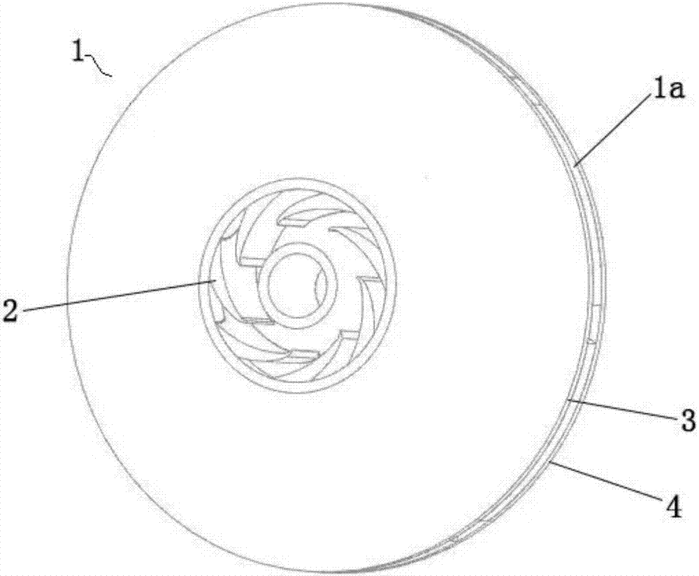
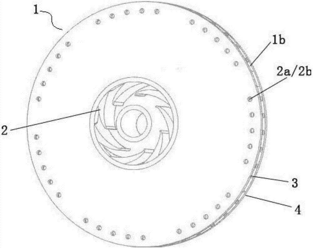
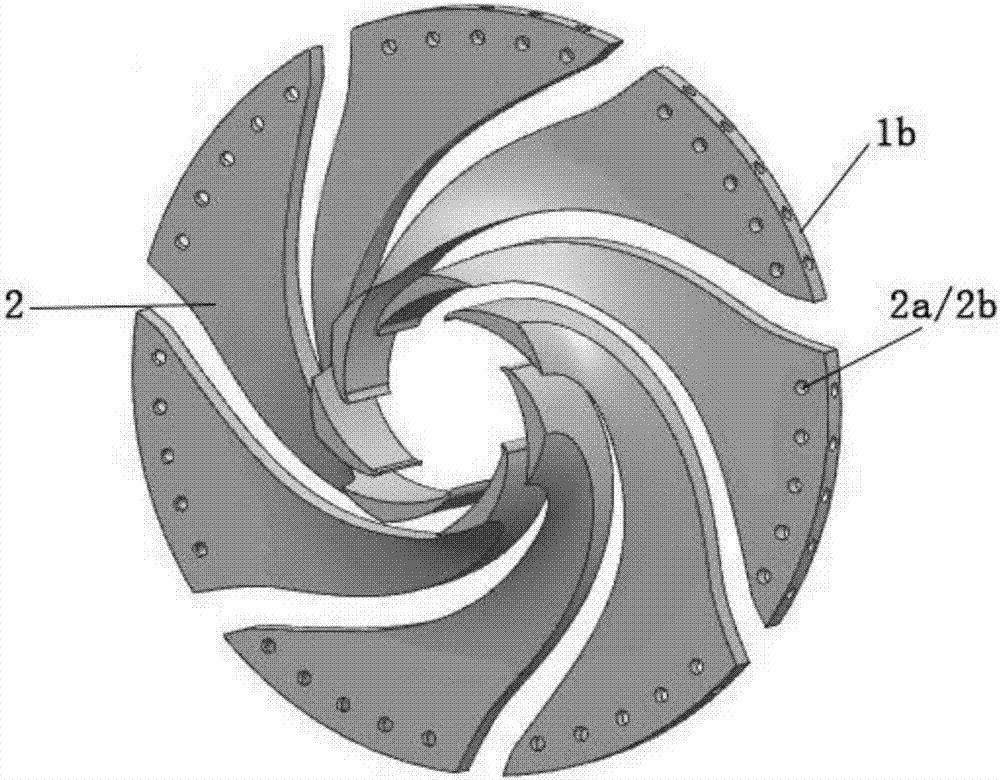
[0032] The ultra-low specific speed centrifugal pump impeller of the present invention, figure 1 , 2 Shown includes front and rear shrouds in the shape of the discs that make up the impeller, figure 2 Contains 6-8 blades with recirculation channels. The front and back molding lines of the blade are composed of multiple arcs and / or straight lines and smooth connections, and the surface of the blade is a ruled surface. Such as image 3 As shown, the front and back sides between adjacent blades constitute the flow path of the impeller and ensure the requirements of the inlet and outlet angles of the b...


PUM


Abstract

The invention discloses a vane wheel of an extra-low specific speed centrifugal pump with circulating flow channels in each edge of an outlet. The vane wheel comprises a front cover plate, a rear cover plate and a plurality of blades between the front cover plate and the rear cover plate, wherein a narrow main flow channel is formed between every two adjacent blades; the sum of the circumferential width of the outlet of the main flow channel is 10-20% of that of the circumference of the outlet of the vane wheel; a mold line of the front surface and the rear surface of each blade is formed by smooth connection of a plurality of sections of arcs and / or straight lines; the surface of each blade is a ruled surface; a plurality of circulating flow channels are uniformly distributed in the edge of each blade outlet in the circumferential direction; and each circulating flow channel is formed by two holes which are separately formed in the radial direction of the vane wheel and parallel to the direction of a rotating shaft of the vane wheel and are intersected and in communication in space. According to the vane wheel disclosed by the invention, the design of the narrow main flow channels is adopted, so that vane channel vortexes and outlet vortexes of the vane wheel can be removed, and the energy loss is reduced; operation lift and operation hydraulic stability under variable working conditions of the extra-low specific speed centrifugal pump can be improved by the small circulating flow channels at the edge of the outlet; and under the condition that the outer diameter of the vane wheel is unchanged is guaranteed, the lift is increased, and the pressure pulsation amplitude in a spiral casing is reduced.

Description

technical field [0001] The invention belongs to the field of mechanical design and manufacture, in particular to the field of design and manufacture of centrifugal pumps, in particular to a design and manufacture technology of impellers of centrifugal pumps with extremely low specific speeds. Background technique [0002] The extremely low specific speed centrifugal pump is mainly used for pumping liquids with small flow rate and high head. The impeller designed according to the existing centrifugal pump design theory and method has a wide flow path between the impeller blades, and the vortex between the blade path and the outlet Large, the pressure pulsation amplitude generated in the volute is large, the efficiency is low, and the stability of the "flow-lift" curve is poor. When specific speed n s If it is lower than 30, the efficiency of centrifugal pumps designed with existing design theories and methods will generally drop below 30%. How to improve the operation stabi...

Claims


Application Information

Patent Timeline
IPC IPC(8): F04D29/22F04D29/24F04D29/66
CPCF04D29/2255F04D29/245F04D29/669
Inventor 赖喜德
Owner XIHUA UNIV
Learn More