
Axial flow fan

A fan and axial technology, applied in the field of axial fans, can solve the problems of high manufacturing cost of secondary fans, and achieve the effect of optimized geometric shape and low air resistance

Inactive Publication Date: 2019-01-01
BORG WARNER INC
View PDF1 Cites 0 Cited by
  • Summary
  • Abstract
  • Description
  • Claims
  • Application Information

AI Technical Summary

Problems solved by technology

[0004] The disadvantage of this construction lies primarily in the relatively high manufacturing outlay involved in arranging and designing the secondary fan, in addition, tests carried out within the framework of the invention have shown that further noise reduction is necessary

Method used


Image

  • Axial flow fan
  • Axial flow fan
  • Axial flow fan

Examples


Embodiment Construction

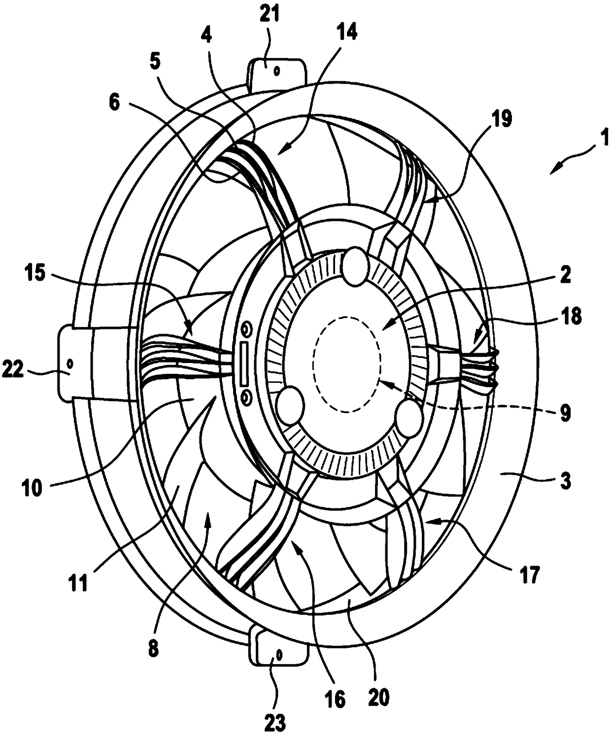
[0029] figure 1 An axial fan 1 according to the invention is shown having a fixed fan hub 2 and a fixed frame 3 comprising the outer circumferential section of the fan hub 2 . Frame 3 is for example ring-shaped, and has a pot-shaped outer contour, and fixing tongue is installed on the outer contour, in figure 1 Three fixing tongues are shown in and identified by reference numerals 21 , 22 and 23 .

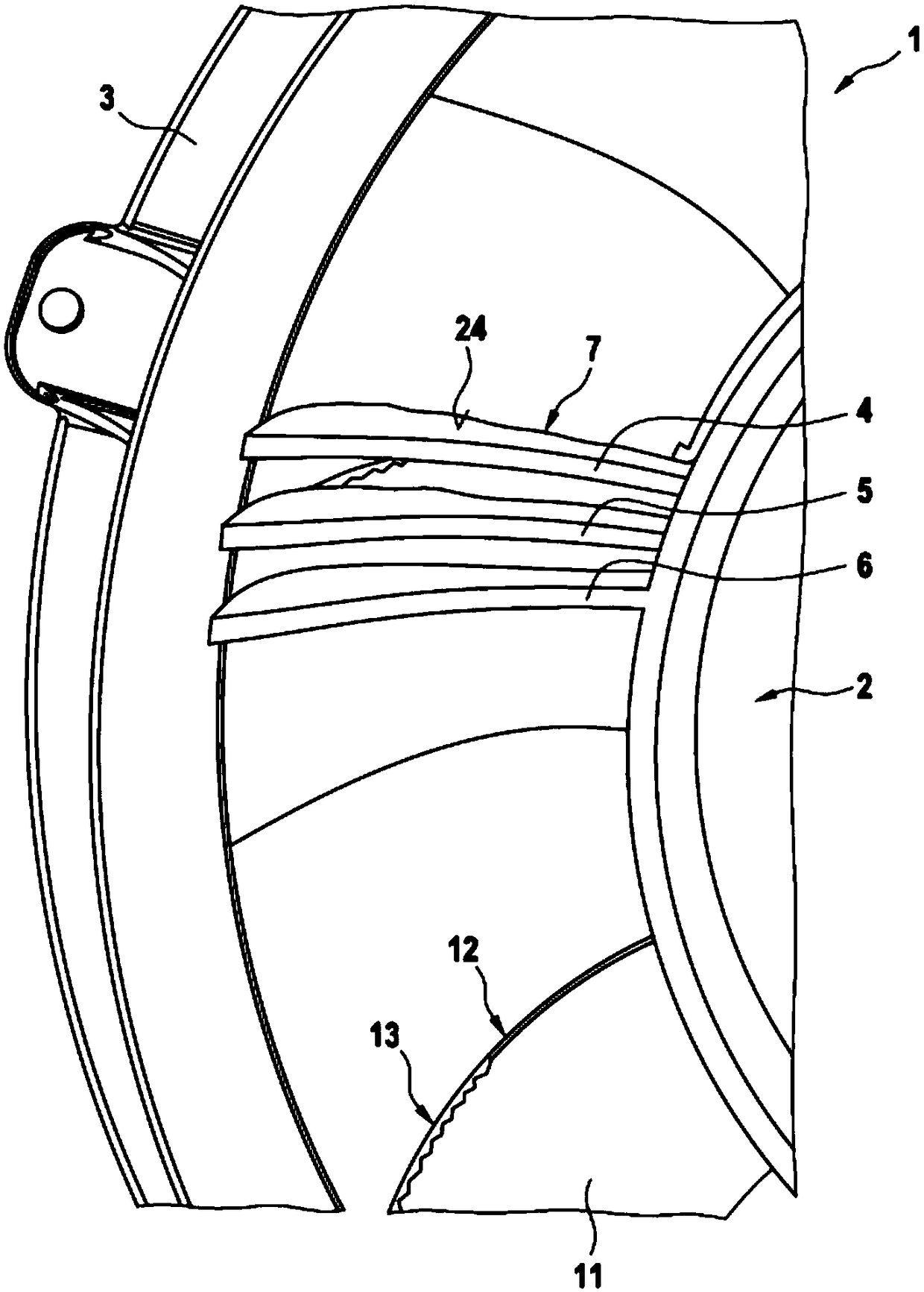
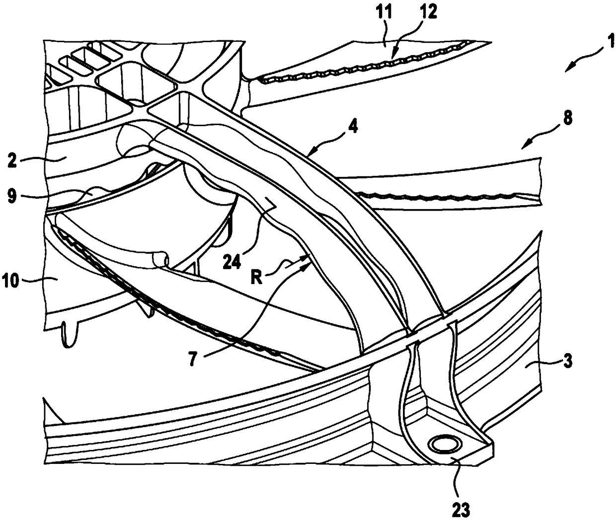
[0030] The fan hub 2 and the frame 3 can be connected to each other through a connecting bar, wherein, in figure 1 The particularly preferred embodiment shown comprises a plurality of connecting strips, three of which are identified with the reference numerals 4 , 5 and 6 . like figure 1 As shown, in the exemplary embodiment a total of 18 such connecting strips 4 , 5 and 6 are provided, each forming three connecting strip groups 14 , 15 , 16 , 17 , 18 or 19 . In the 3 connecting strip sets 14 to 19, the connecting strips 4, 5 and 6 are arranged closely adjacent to each other, a...


PUM


Abstract

The invention relates to an axial flow fan (1) comprising a stationary hub (2); comprising an annular stationary frame (3), which surrounds the hub (2) on the outer peripheral side and which is connected to the stationary hub (2) via at least one strut (4, 5, 6); and comprising a fan wheel (8), which is in drive connection with a fan wheel drive (9), which has a rotating fan wheel hub (10), and which has a plurality of fan wheel blades (11), which each comprise a back edge (12), characterized in that the contour of the strut (4, 5, 6) is designed as sine wave shaped, and wherein the back edge(12) is preferably designed as toothed at least in a partial area (13).

Description

technical field [0001] The invention relates to an axial fan according to the preamble of claim 1 . Background technique [0002] An axial fan of this type is known from DE 10 2010 039 219 A1. For this type of axial fan, in addition to achieving maximum aerodynamic efficiency, it is also necessary to suppress the noise generated by the air when the fan blows air. [0003] To achieve this aim, DE 10 2010 039 219 A1 describes a fan which is especially suitable as a motor vehicle engine cooling fan, for which fan a fixed frame encloses a rotating fan wheel which is contained by a fan housing Wrapped fan blades, for which the fan case and frame form a gap. Furthermore, the invention according to this patent specification is provided with a secondary fan which suppresses the backflow of the air conveyed by the fan wheel. The secondary fan can, for example, be a component of a fan wheel, which in a preferred embodiment consists of secondary fan blades mounted on the fan housing...

Claims


Application Information

Patent Timeline
IPC IPC(8): F04D25/08F04D29/32F04D29/38F04D29/54F04D29/66
CPCF04D25/08F04D29/329F04D29/388F04D29/541F04D29/661F04D29/666F04D19/002F04D29/328F04D29/384F04D29/542F04D29/667F05D2240/304F05D2250/184F05D2250/611F04D29/522
Inventor T·莫泽F·哈泽
Owner BORG WARNER INC
Learn More