Blade head overhanging type runner

A blade and runner technology, applied in the field of blade head cantilever runners, can solve problems such as the inability to effectively improve the internal flow state of the cavity, and the inability to significantly reduce the adverse effects of the S-characteristic pressure pulsation of the pump turbine.

Active Publication Date: 2019-11-05
DONGFANG ELECTRIC MACHINERY
View PDF10 Cites 0 Cited by
  • Summary
  • Abstract
  • Description
  • Claims
  • Application Information

AI Technical Summary

Problems solved by technology

[0009] The Francis runner used for hydraulic machinery disclosed in this patent document relates to the radius change of the blade height direction of the Francis runner: the middle radius is the smallest, the upper and lower ends are large, and the bending direction of the water inlet edge is concave. This geometric feature It cannot better guide the water flow into the runner channel, especially it cannot effectively improve the internal flow state of the cavity in front of the runner under partial load or no-load conditions, and it cannot significantly reduce the defects caused by the S characteristic and pressure pulsation of the pump turbine. influences

Method used


Image

  • Blade head overhanging type runner
  • Blade head overhanging type runner
  • Blade head overhanging type runner

Examples


Embodiment 1

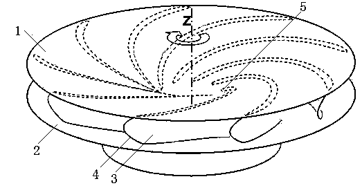
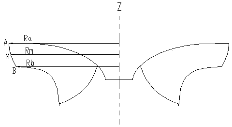
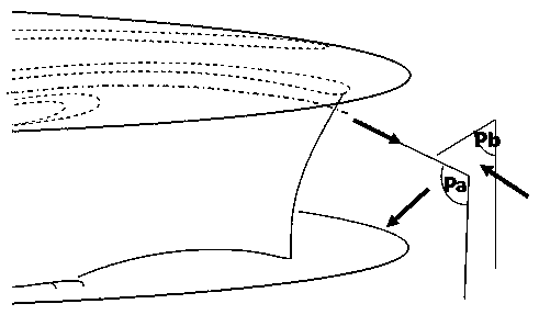
[0031] see Figure 1-Figure 5, a blade head cantilever type runner, comprising an upper crown 1, a lower ring 2 and a plurality of blades 3, the upper crown 1 and the lower ring 2 are rotationally symmetrical about the rotation axis of the runner, and the blades 3 include a water inlet edge 4 and the water outlet edge 5, the blade 3 is located between the upper crown 1 and the lower ring 2, the blade 3 is connected with the upper crown 1 and the lower ring 2 respectively, and the intersecting line formed by the connection between the blade 3 and the upper crown 1 is the blade upper crown shape line , the intersecting line formed by the connection between the blade 3 and the lower ring is the lower ring profile line of the blade, the intersection point of the water inlet edge 4 and the upper crown 1 is A, the intersection point of the water inlet edge 4 and the lower ring 2 is B, and the water outlet The intersection point between the side 5 and the upper crown 1 is C, the inte...

Embodiment 2

[0038] see Figure 1-Figure 5 , a blade head cantilever type runner, comprising an upper crown 1, a lower ring 2 and a plurality of blades 3, the upper crown 1 and the lower ring 2 are rotationally symmetrical about the rotation axis of the runner, and the blades 3 include a water inlet edge 4 and the water outlet edge 5, the blade 3 is located between the upper crown 1 and the lower ring 2, the blade 3 is connected with the upper crown 1 and the lower ring 2 respectively, and the intersecting line formed by the connection between the blade 3 and the upper crown 1 is the blade upper crown shape line , the intersecting line formed by the connection between the blade 3 and the lower ring is the lower ring profile line of the blade, the intersection point of the water inlet edge 4 and the upper crown 1 is A, the intersection point of the water inlet edge 4 and the lower ring 2 is B, and the water outlet The intersection point between the side 5 and the upper crown 1 is C, the int...

Embodiment 3

[0043] see Figure 1-Figure 5 , a blade head cantilever type runner, comprising an upper crown 1, a lower ring 2 and a plurality of blades 3, the upper crown 1 and the lower ring 2 are rotationally symmetrical about the rotation axis of the runner, and the blades 3 include a water inlet edge 4 and the water outlet edge 5, the blade 3 is located between the upper crown 1 and the lower ring 2, the blade 3 is connected with the upper crown 1 and the lower ring 2 respectively, and the intersecting line formed by the connection between the blade 3 and the upper crown 1 is the blade upper crown shape line , the intersecting line formed by the connection between the blade 3 and the lower ring is the lower ring profile line of the blade, the intersection point of the water inlet edge 4 and the upper crown 1 is A, the intersection point of the water inlet edge 4 and the lower ring 2 is B, and the water outlet The intersection point between the side 5 and the upper crown 1 is C, the int...


PUM


Abstract

The invention discloses a blade head overhanging type runner, and belongs to the technical field of hydraulic machine equipment. An upper crown, a lower ring and a plurality of blades are included. The blade head overhanging type runner is characterized in that each blade comprises a water inlet edge and a water outlet edge, wherein the intersection point of the water inlet edge and the upper crown is A, the intersection point of the water inlet edge and the lower ring is B, the intersection point of the water outlet edge and the upper crown is C, and the intersection point of the water outletedge and the lower ring is D; and the water inlet edge and the water outlet edge of at least one blade are bent, the blades are concaved towards the inner side of the runner, the distance between anypoint P on each water inlet edge and the straight line between the corresponding point A and the corresponding point B is maximal at the middle point M of the corresponding water inlet edge, the radius Ra of each intersection point A is larger than the radius Rb of the corresponding intersection point B, the radius Rm of each middle point M is larger than the radius Ra of the corresponding intersection point A, and the radius Rm of each middle point M is larger than the radius Rb of the corresponding interaction point B. By means of the blade head overhanging type runner, the S character andpressure pulsation performance of a water pump water turbine can be improved, and a unit can be more stable in the grid connection process through the special geometrical characteristic of the runnerblades.

Description

technical field [0001] The invention relates to the technical field of hydraulic mechanical equipment, in particular to a blade head cantilevered runner. Background technique [0002] With the rapid development of pumped storage power plants, the stability of pump turbines has attracted more and more attention from the industry. Whether the units can be quickly and stably connected to the grid during peak regulation and frequency regulation has an important impact on the normal operation of the power system. However, at present, the entry and exit sides of traditional pump turbine runners are usually a straight line. The S characteristics and pressure pulsation characteristics of such runners are generally poor, and there is a risk that they cannot be smoothly connected to the grid during operation. [0003] The runner includes an upper crown, a lower ring and a plurality of blades mounted between them. When the hydraulic machinery is in the turbine mode, the water flows in...

Claims


Application Information

Patent Timeline
Patent Type & Authority Applications(China)
IPC IPC(8): F03B3/02F03B3/12F03B11/04
CPCF03B3/02F03B3/121F03B3/125F03B11/04Y02E10/20
Inventor 梁权伟程宦郑津生胡江艺林方舟凡家异刘德民刘伟超陈舰
Owner DONGFANG ELECTRIC MACHINERY
Why Eureka
Try Eureka