Garbage incineration gas inlet intelligent control system

An intelligent control system and waste incineration technology, applied in the direction of incinerators, combustion methods, combustion types, etc., can solve problems such as complex raw materials, ambient air, water source and soil pollution, and fly ash emissions

Inactive Publication Date: 2017-08-18
SINOBIOWAY DINGHE ENVIRONMENTAL PROTECTION CO LTD
View PDF4 Cites 0 Cited by
  • Summary
  • Abstract
  • Description
  • Claims
  • Application Information

AI Technical Summary

Problems solved by technology

How to deal with these domestic wastes has been a major problem that has plagued people's lives for many years. Over the years, people first used the landfill method. Later, people found that the landfilled garbage cannot change the nature of the garbage, and it will take up a lot of land. The vacant space, especially the garbage such as plastic bags, cannot change its nature after being landfilled. There are not many things, and at the same time, new sources of garbage pollution will be produced and it will end
Later, the method of incineration was used. It is relatively thorough to use this method to dispose of garbage. However, the flue gas in the waste incinerator is discharged into the atmosphere through the chimney. Due to the high cost of flue gas treatment and operation or the Due to the lack of maintenance of the gas treatment system and other reasons, a large amount of flue gas containing toxic and harmful gases and fly ash is discharged, causing serious pollution to the ambient air, water sources and soil. The long-term emission of these flue gases will endanger the living environment of human beings.
In addition, most of the garbage contains a lot of water. Due to the high water content, the cost of incineration is high and the air pollution is also high. Therefore, it is imperative to improve the technology of incineration of garbage.

Method used


Image

  • Garbage incineration gas inlet intelligent control system
  • Garbage incineration gas inlet intelligent control system

Examples


Embodiment Construction

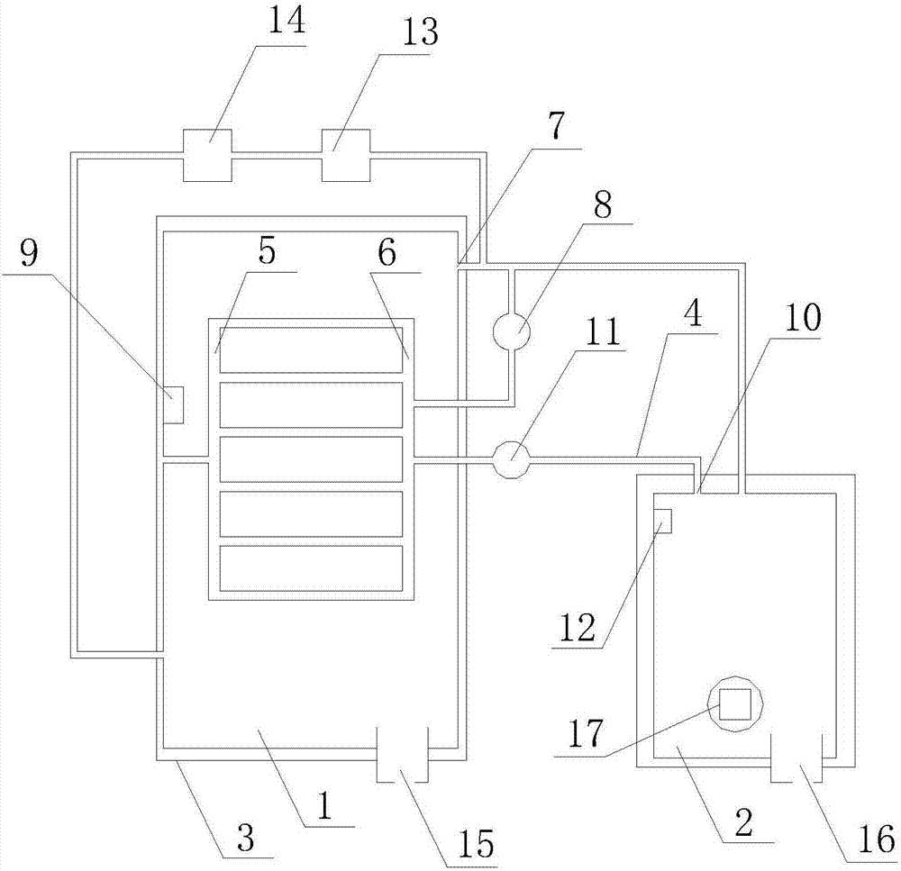
[0023] Such as figure 1 , figure 2 as shown, figure 1 , figure 2 It is an intelligent air intake control system for waste incineration proposed by the present invention.

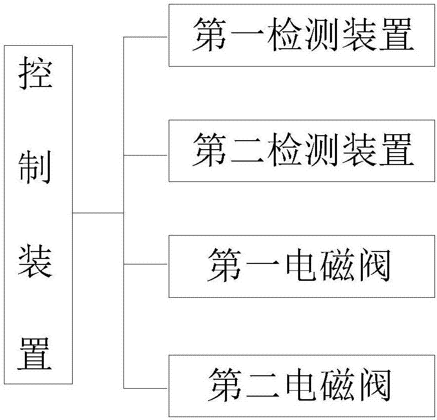
[0024] refer to figure 1 , figure 2 , the waste incineration air intake intelligent control system proposed by the present invention includes: a first cavity 1, a second cavity 2, a casing 3, an exhaust gas channel 4, and a control device;

[0025] The first cavity 1 is arranged inside the shell 3, and a gas channel for gas circulation is formed between the outer wall of the first cavity 1 and the inner wall of the shell 3, and a first pipeline 5 and a second pipeline are arranged vertically inside the first cavity 1 6. The first pipeline 5 is in communication with the gas passage pipeline, and a plurality of horizontal pipelines are arranged between the first pipeline 5 and the second pipeline 6, and one end of the above-mentioned multiple horizontal pipelines is connected with the first pipeline 5,...


PUM


Abstract

The invention discloses a garbage incineration gas inlet intelligent control system which comprises a first cavity, a second cavity, a shell, a tail gas channel and a control device. The first cavity is formed in the shell and provided with an exhaust opening. The exhaust opening communicates with a second pipeline through a pipeline, and a first solenoid valve is arranged on the above communicating pipeline. A first detection device is arranged in the first cavity and used for detecting the temperature value T of the first position in the first cavity. A tail gas outlet is formed in the second cavity and communicates with a second pipeline through the tail gas channel, and a second solenoid valve is arranged on the tail gas channel. A second detection device is arranged in the second cavity and used for detecting the temperature value T0 of the tail gas outlet. The control device carries out command control over action of the first solenoid valve and the second solenoid valve by acquiring the temperature value T of the first detection device and acquiring the temperature value T0 of the second detection device through the comparative results of T and T1, T and T2 and T0 and T3.

Description

technical field [0001] The invention relates to the technical field of waste incineration treatment, in particular to an intelligent control system for waste incineration air intake. Background technique [0002] With the continuous development of the economy and the acceleration of urbanization, the amount of municipal solid waste generated every year has doubled. How to deal with these domestic wastes has been a major problem that has plagued people's lives for many years. Over the years, people first used the landfill method. Later, people found that the landfilled garbage cannot change the nature of the garbage, and it will take up a lot of land. The vacant space, especially the garbage such as plastic bags, cannot change its nature after being landfilled. There are not many things, and at the same time, new sources of garbage pollution will come to an end. Later, the method of incineration was used. It is relatively thorough to use this method to dispose of garbage. H...

Claims


Application Information

Patent Timeline
Patent Type & Authority Applications(China)
IPC IPC(8): F23G5/50F23G5/16F23G5/46F23G5/04
CPCF23G5/50F23G5/04F23G5/16F23G5/46F23G2201/10F23G2202/103F23G2206/10F23G2207/101
Inventor 曹文波张文锐魏凌敏舒志强唐武才李启仁李文龙郎志中
Owner SINOBIOWAY DINGHE ENVIRONMENTAL PROTECTION CO LTD
Why Eureka
Try Eureka