Device and method for online analysis and detection of mechanical property of solid wood board by utilizing laser measurement fiber angle
A technology of laser measurement and fiber angle, which is used in measurement devices, material analysis, material analysis by optical means, etc., can solve the problems of waste detection error, test piece damage, inability to general inspection of the whole batch of plates, etc., to increase detection Speed, low detection error, and the effect of increasing detection efficiency
- Summary
- Abstract
- Description
- Claims
- Application Information
AI Technical Summary
Problems solved by technology
Method used
Image
Examples
specific Embodiment approach 1
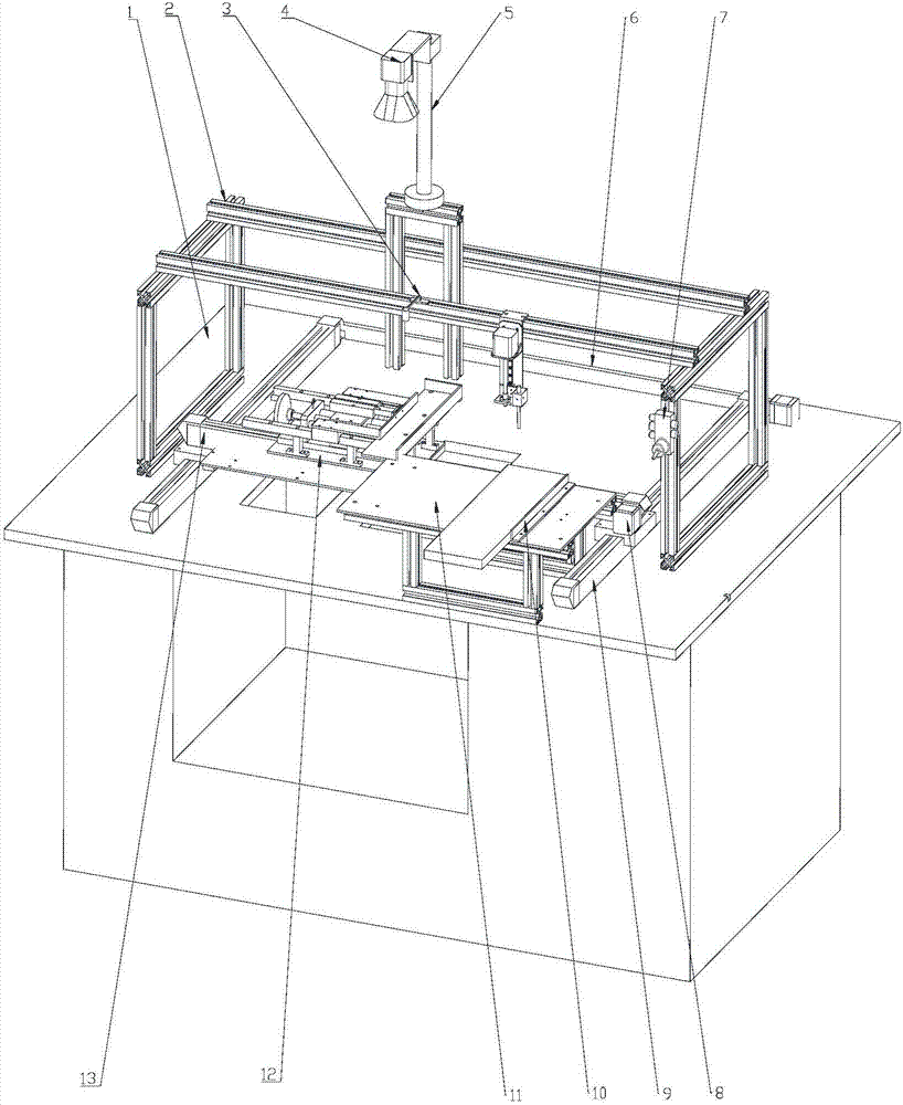
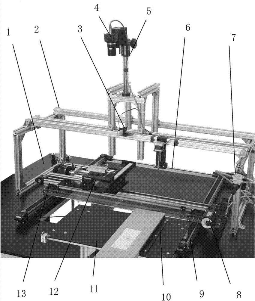
[0025] Specific implementation mode one: combine figure 1 Describe this embodiment, the device that utilizes the on-line analysis of laser to measure the fiber angle of this embodiment to detect the mechanical properties of solid wood panels includes a workbench 1, a test bench main support frame 2, a laser generator 3, a camera 4 (with a lens), and the height of the camera Adjusting frame 5, synchronous drive shaft 6, horizontal motion stepping motor 8, longitudinal motion stepping motor, mobile clamping device 12 (including pneumatic clamping device) and two-axis slide table;
[0026] The two-axis slide table includes two longitudinal guide rail modules 9 and a transverse guide rail module 13, and the two longitudinal guide rail modules 9 are fixedly arranged on the board surface of the workbench 1; The longitudinal guide rail module 9, and the two longitudinal guide rail modules 9 move synchronously through the synchronous drive shaft 6; each longitudinal guide rail module...
specific Embodiment approach 2
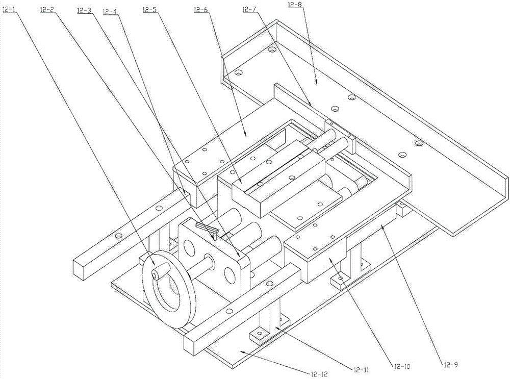
[0030] Specific implementation mode two: combination figure 2 Describe this embodiment, the difference between this embodiment and specific embodiment 1 is: the mobile clamping device (including pneumatic clamping device) 12 includes:
[0031] Hand wheel 12-1, hand wheel lock 12-2, sliding table 12-3, first splint slide rail 12-4, cylinder 12-5, movable splint 12-6, rubber strip 12-7, static splint 12-8 , the second splint slide rail 12-9, the splint slider 12-10, the support frame 12-11, the main base plate 12-12 of the mobile clamping device;
[0032] The first splint slide rail 12-4 and the second splint slide rail 12-9 are respectively symmetrically fixed on the main base plate 12-12 of the mobile clamping device through two supports 12-11; the first splint slide rail 12-4 and the second splint slide rail 12-4 A splint slider 12-10 is respectively arranged on the two splint slide rails 12-9, and two splint slide blocks 12-10 slide on the second splint slide rail 12-9 and...
specific Embodiment approach 3
[0037] Specific embodiment three: the difference between this embodiment and specific embodiment one or two is that: the device also includes a loading platform limit rib 10 and a loading platform 11, and the loading platform 11 is located on the workbench 1, and the loading The stage limit rib 10 is located on one side of the object stage 11 and is used to limit the position of the plate to be measured on the object stage 11 .
[0038] The mobile clamping device 12 moves to the loading position, the loading position is the position where the edge of the stationary splint 12-8 is aligned with the sidewall 10 of the stage, and the plate to be measured on the stage 11 is manually pushed into the mobile clamping device 12, until the front end of the plate to be tested touches the front end of the stationary splint 12-8; turn the pneumatic switch 7 to the clamping position of the movable splint 12-6; the movable splint 12-6 is pushed forward by the cylinder 12-5, Clamp the plate t...
PUM
 Abstract
Description
Claims
Application Information
 - R&D
- Intellectual Property
- Life Sciences
- Materials
- Tech Scout
- Unparalleled Data Quality
- Higher Quality Content
- 60% Fewer Hallucinations
Browse by: Latest US Patents, China's latest patents, Technical Efficacy Thesaurus, Application Domain, Technology Topic, Popular Technical Reports.
© 2025 PatSnap. All rights reserved.Legal|Privacy policy|Modern Slavery Act Transparency Statement|Sitemap|About US| Contact US: help@patsnap.com


