
Control method for controlling flight region of unmanned plane

A control method and UAV technology, applied in the field of UAV flight area control, can solve the problems of obstacle response, failure to take into account the operation mode of UAV, and inability to adapt to the high maneuverability of UAV.

Active Publication Date: 2017-08-18
GUANGXI UNIV
View PDF9 Cites 18 Cited by
  • Summary
  • Abstract
  • Description
  • Claims
  • Application Information

AI Technical Summary

Problems solved by technology

And when performing actual tasks, UAVs often perform multiple different tasks, and cannot respond to obstacles in time in the case of offline path planning
Most of the existing path planning methods for UAVs are offline planning methods, which cannot adapt to the high mobility of UAVs, and do not take into account the actual operation mode of UAVs.

Method used


Image

  • Control method for controlling flight region of unmanned plane
  • Control method for controlling flight region of unmanned plane
  • Control method for controlling flight region of unmanned plane

Examples


specific Embodiment

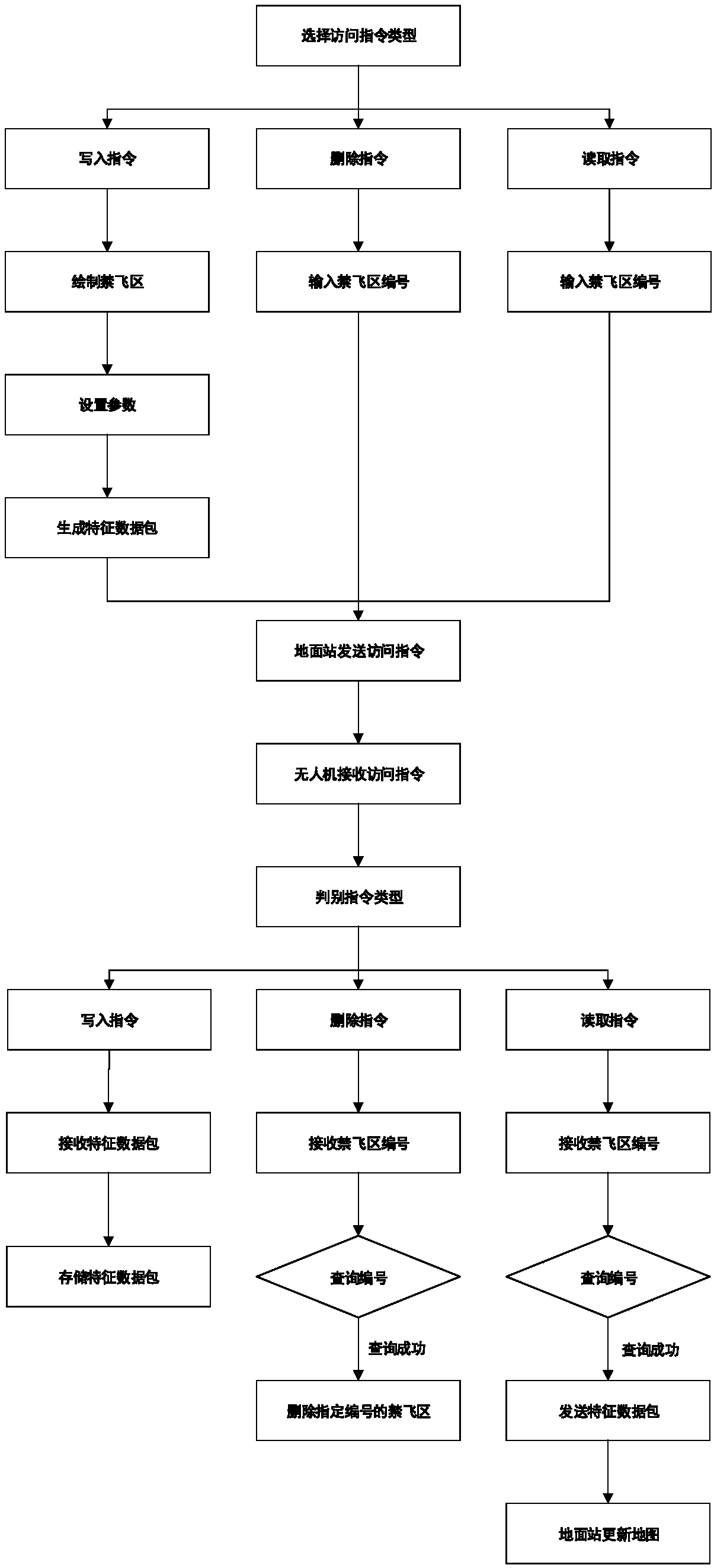
[0083] Such as figure 1 Shown, a kind of visit and operation method of no-fly zone, wherein the visit of no-fly zone comprises the following steps:

[0084] S01: Select the type of access command at the ground station, the command type includes write command, delete command and read command;

[0085] S02: Input different command parameters at the ground station according to different command types. To write a command, you need to draw a no-fly zone, set parameters and generate a characteristic data packet. To delete and read commands, you need to input the no-fly zone label;

[0086] When writing a polygonal no-fly zone, select the type of no-fly zone on the ground station as polygon, and select several vertices on the map of the ground station, and input the height of the no-fly zone, speed limit coefficient, and maximum constant velocity after confirmation. When drawing a circular obstacle, select the type of no-fly zone on the ground station as a circle, and select the cen...


PUM


Abstract

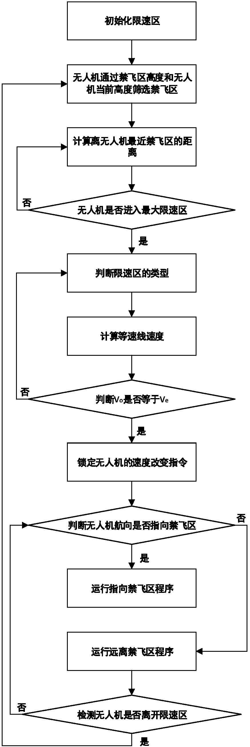
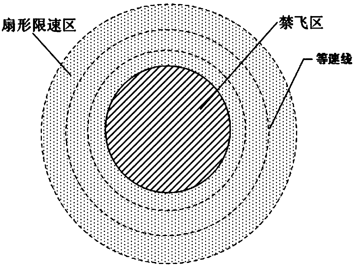
The present invention discloses a control method for controlling the flight region of an unmanned plane. The method comprises an access method and an operation method for the flight no-fly zone of an unmanned plane. The no-fly zone has the following properties: number, type, height, speed-limiting factor, maximum constant speed line speed, and characteristic parameter. Based on the method, the no-fly zone can be drawn on a ground station and then transmitted to the flight controller of the unmanned plane. The no-fly zone may be a practical obstacle, and can also be a manually defined region. Meanwhile, a speed-limiting region running method is provided for preventing the unmanned plane to enter the no-fly zone. As a result, the unmanned plane is ensured not to enter the no-fly zone.

Description

technical field [0001] The invention relates to the field of aircraft guidance and control, in particular to a method for controlling the flight area of ​​an unmanned aerial vehicle. Background technique [0002] The aircraft guidance and control in navigation guidance and control is to enable the UAV to complete the set goals autonomously. During the actual flight, the UAV can use its own sensors such as (laser range finder, microwave radar, depth camera, etc.) to detect surrounding obstacles and terrain. However, some man-made no-fly areas (such as airports, military sensitive areas) or invisible threat areas (such as near high-voltage lines and above the water surface) cannot be detected by sensors. Drones are highly maneuverable and require a certain amount of reaction time to slow down or hover. And when performing actual tasks, UAVs often perform multiple different tasks, and cannot respond to obstacles in time in the case of offline path planning. Most of the exist...

Claims


Application Information

Patent Timeline
IPC IPC(8): G05D1/10
CPCG05D1/101
Inventor 林靖宇徐健
Owner GUANGXI UNIV
Learn More