Monocular vision-based lane line and front obstacle detection method

An obstacle detection and monocular vision technology, applied in the field of image processing, can solve the problems of inaccurate detection of lane lines and low detection accuracy of obstacles ahead, and achieve the goals of reducing the total amount of calculation, improving driving safety, and improving recognition accuracy Effect

Inactive Publication Date: 2017-08-18
HARBIN INST OF TECH
View PDF2 Cites 37 Cited by
  • Summary
  • Abstract
  • Description
  • Claims
  • Application Information

AI Technical Summary

Problems solved by technology

[0005] The purpose of the present invention is to solve the shortcomings of inaccurate detection of lane lines and low detection accu

Method used


Image

  • Monocular vision-based lane line and front obstacle detection method
  • Monocular vision-based lane line and front obstacle detection method
  • Monocular vision-based lane line and front obstacle detection method

Examples


specific Embodiment approach 1

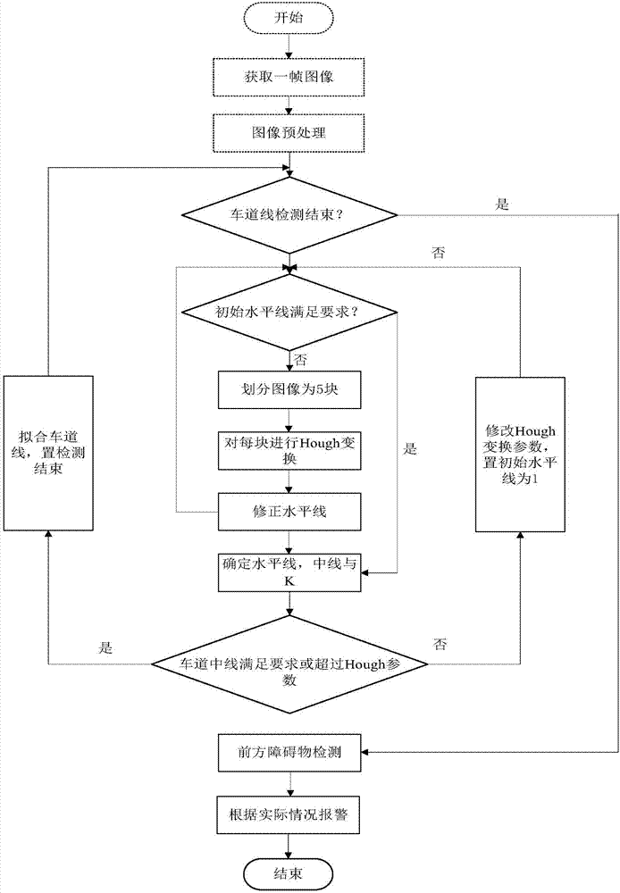
[0045] Specific implementation mode one: combine figure 1 To illustrate this embodiment, the specific process of a method for detecting lane lines and obstacles ahead based on monocular vision in this embodiment is as follows:

[0046] Step 1, using a vehicle-mounted CCD camera to obtain an original image, and performing grayscale processing on the original image to obtain a grayscale image;

[0047] Step 2, preprocessing the grayscale image to obtain a binarized image after removing clutter;

[0048] Step 3. Carry out the initial detection of the lane line in the near half area and the detection of the line pressure alarm based on the Hough transform on the binarized image after the clutter is removed;

[0049] Step 4, according to the point coordinates on the initial detection line of the lane line in the near half area obtained in step 3, carry out parabola fitting to the lane line in the near field of vision and the lane line in the far field of view, to obtain the fitte...

specific Embodiment approach 2

[0051] Specific embodiment 2: The difference between this embodiment and specific embodiment 1 is that the grayscale image is preprocessed in the step 2; the preprocessing includes binarization and filtering of the grayscale image; the binary value after removing clutter is obtained Image; the specific process is:

[0052] Step 21. Perform binary preprocessing on the grayscale image to obtain a binary image; the specific process is:

[0053] Step 22: Filtering and preprocessing the binarized image to obtain a binarized image after removing clutter.

[0054] Other steps and parameters are the same as those in Embodiment 1.

specific Embodiment approach 3

[0055] Embodiment 3: The difference between this embodiment and Embodiment 1 or 2 is that in the step 21, the grayscale image is subjected to binarization preprocessing to obtain a binarization image; the specific process is:

[0056] The gray threshold segmentation algorithm is used to process each row of the gray image, and the gray threshold of each row is set between the maximum gray value of each row and the average gray value of the row, which can accurately segment the lane and the background, namely: RowAvg [i]

[0057] Among them: RowAvg[i] is the average gray value of row i; MaxGray[i] is the maximum gray value of row i; T[i] is the gray threshold of row i; the value of i is a positive integer, such as 240;

[0058] In order to simplify the complexity of the algorithm, select a scale factor R, 0

[0059] T[i]=RowAvg[i]+(MaxGray[i]-RowAvg[i])*R

[0060] * is the multiplication sign.

[0061] Other steps and parameters are the same as t...


PUM


Abstract

The invention discloses a monocular vision-based lane line and front obstacle detection method, which relates to a lane line detection and front obstacle detection method and aims at solving defects of inaccurate lane line detection and low front obstacle detection precision in the prior art. The method particularly comprises steps: 1, a vehicle-mounted CCD camera is adopted to acquire an original image, gray processing is carried out on the original image, and a gray image is obtained; 2, the gray image is pre-processed, and a binary image after clutter removal is obtained; 3, the binary image after clutter removal is subjected to near half area lane line initial detection and line crossing alarming detection based on Hough transform; 4, according to point coordinates on the near half area lane line initial detection line obtained in the third step, parabolic fit is carried out on a near-view field lane line and a far-view field lane line, and a fit lane line is obtained; and 5, obstacle detection is carried out in the fit lane line obtained in the fourth step. The method is applied to the technical field of image processing.

Description

technical field [0001] The invention relates to lane line detection and front obstacle detection methods. Involved in the field of image processing technology. Background technique [0002] Lane marking is the most basic traffic sign, and it is also a basic and necessary function in the lane departure system. It not only provides a reference for navigation, but also applies to functions such as moving target detection and automobile accident warning. [0003] Most of the lane departure systems use the lateral position of the vehicle in the lane as a basis for calculating whether the warning occurs or not. These systems can be divided into two categories: road infrastructure based systems and vehicle based systems. The lane line detection based on monocular vision belongs to the latter. Vehicle-based lane departure warning systems use machine vision or infrared sensors to detect the position of lane markings. According to the installation method of the sensors, they can b...

Claims


Application Information

Patent Timeline
IPC IPC(8): G06K9/00
CPCG06V20/588G06V20/58
Inventor 高建军宿富林徐新博
Owner HARBIN INST OF TECH
Why Eureka
Try Eureka