An RFID-based intelligent electronic control device for electric door locks and its working method

An electronic control device, electric lock technology, applied in the direction of instruments, single input port/output port register, time register, etc., can solve the problem that the RFID radio frequency signal is easily affected by the crystal oscillator circuit of the single-chip microcomputer, the security is low, and it is not suitable for Extensive use and other problems, to achieve the effect of convenient fault inquiry and maintenance, high safety and reliability

Active Publication Date: 2019-07-09
辽宁鼎汉奇辉电子系统工程有限公司
View PDF6 Cites 0 Cited by
  • Summary
  • Abstract
  • Description
  • Claims
  • Application Information

AI Technical Summary

Problems solved by technology

[0003] 1. The RFID radio frequency signal is easily affected by the crystal oscillator circuit of the single-chip microcomputer, and the reliability and stability are poor;
[0004] 2. Using fixed code transmission without encryption processing, the signal is easy to be cracked and copied, and the security is extremely low;
[0005] 3. Most of the equipment control circuits adopt a single circuit design. Once damaged, the door can only be opened by destroying the door, causing unnecessary trouble and economic loss;
[0006] 4. If intelligent control function is required, the failure rate is high and the equipment price is relatively expensive, so it is not suitable for mass use

Method used


Image

  • An RFID-based intelligent electronic control device for electric door locks and its working method
  • An RFID-based intelligent electronic control device for electric door locks and its working method
  • An RFID-based intelligent electronic control device for electric door locks and its working method

Examples


Embodiment Construction

[0034] The specific content of the present invention will be described in detail below with reference to the accompanying drawings.

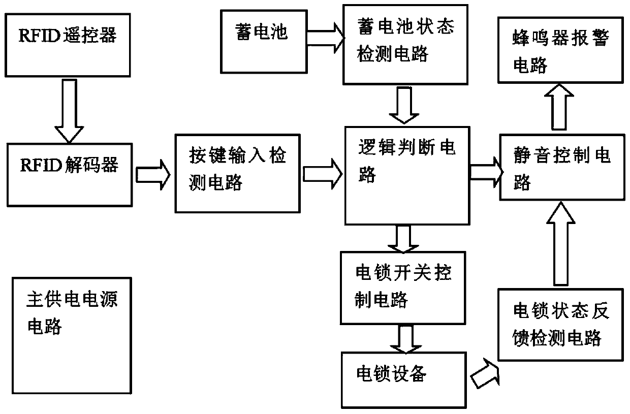
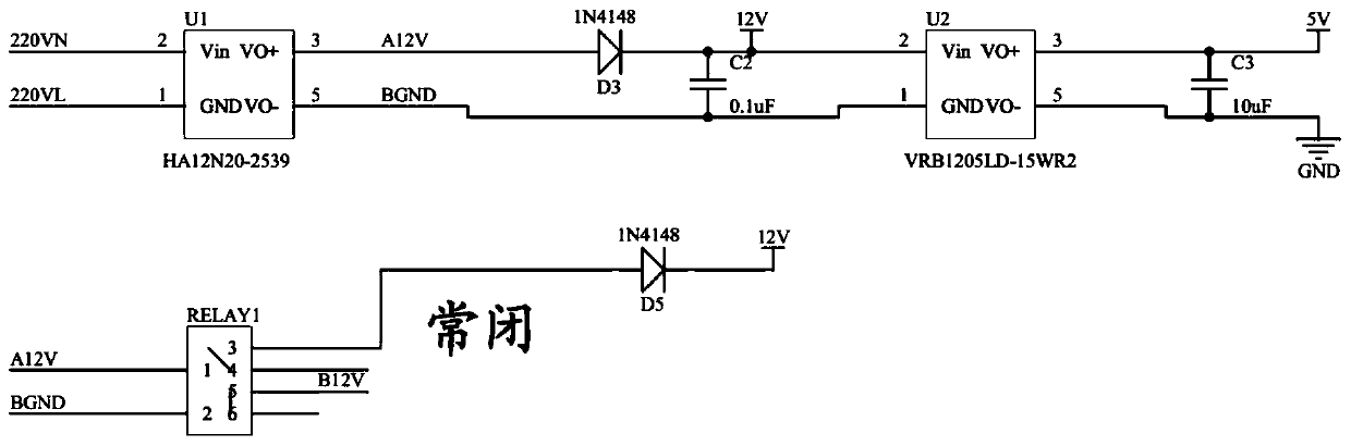
[0035] Such as figure 1 Shown is the overall working principle of the present invention. The power supply of the present invention consists of a main power supply and a backup battery power supply. When the power grid is normal, 220V AC power is used, and when the power fails, a backup 12V battery is used to power the equipment. When the handheld remote control (four buttons) with the HCS301 rolling code chip as the core sends RFID signals to the intelligent electronic control device, the RFID decoder TDH6301 chip in the device converts the RFID signals into four TTL level signals (D0~D3). ), corresponding to the four buttons on the remote control. In addition, when there is any button input, an additional TTL level signal (VT) is generated and output in the form of pulse (that is, a pulse signal is output when the button is pressed), RFID The TTL ...


PUM


Abstract

The invention discloses an intelligent electric control device for an electric door lock based on RFID and a working method thereof. The device comprises an RFID remote controller, an RFID decoder, a logical judgment circuit, an electric lock switch control circuit, a silence control circuit, an electric lock state feedback detection circuit, a buzzer warning circuit and a storage battery state detection circuit. According to the invention, the device is kept in a normally closed lock state when no operation is executed after electrifying, so that the locking state of a vehicle door can be kept after the power supply of the device recovers the normal power supply under the condition of accident outage or unstable instantaneous voltage. The logical judgment circuit, the electric lock state feedback detection circuit and the electric lock switch control circuit of the device are all arranged as double-loop redundant protecting circuits, and the damage to one circuit can not result in control failure. The device disclosed by the invention is suitable for an economical RFID intelligent electric control device adopted by the railway industry; the intelligent electric control device can be used together with a common electric door lock; and an RFID radio-frequency signal is not interfered while the safety and reliability are ultrahigh.

Description

Technical field [0001] The invention relates to an electric door lock, in particular to an electric control device of an electric door lock applied to the encrypted remote control door of a moving freight car in the railway industry. Background technique [0002] At present, the most widely used remote control door device in the railway industry uses a fixed code to transmit RFID radio frequency signals, and the control circuit is realized by a single-chip microcomputer without redundant protection. This common remote control method has the following disadvantages: [0003] 1. RFID radio frequency signals are easily affected by the single-chip crystal oscillator circuit, and the reliability and stability are poor; [0004] 2. Using fixed code transmission without encryption processing, the signal is easy to be cracked and copied, and the security is extremely low; [0005] 3. The control circuit of the equipment mostly adopts single circuit design. Once damaged, the door can only be ...

Claims


Application Information

Patent Timeline
Patent Type & Authority Patents(China)
IPC IPC(8): G07C9/00
CPCG07C9/00182G07C9/00571G07C2009/00634
Inventor 徐起力张蔚徐恺
Owner 辽宁鼎汉奇辉电子系统工程有限公司
Why Eureka
Try Eureka