Devices, Systems And Methods For Aiming Directional Antennas

An antenna and directional technology, applied in the field of reliable communication and methods, can solve problems such as poor quality signals, and achieve the effects of high signal level, high data throughput, and reliable communication

Inactive Publication Date: 2017-08-18
TAOGLAS GROUP HLDG LTD
View PDF22 Cites 1 Cited by
  • Summary
  • Abstract
  • Description
  • Claims
  • Application Information

AI Technical Summary

Problems solved by technology

[0005] The disadvantage of a high-gain directional antenna becomes most pronounced without knowledge of the location of the remote site, providing a signal of poor quality in every direction except its specific alignment

Method used


Image

  • Devices, Systems And Methods For Aiming Directional Antennas
  • Devices, Systems And Methods For Aiming Directional Antennas
  • Devices, Systems And Methods For Aiming Directional Antennas

Examples


example 1

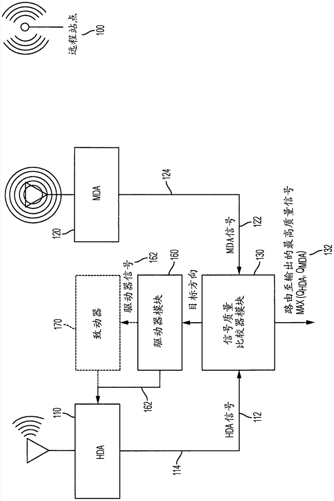
[0073] When using this system in a satellite, the system can be configured to rotate clockwise at 5 degrees through 360 degree increments, then in 5 degree increments of lift, and then in reverse if necessary before repeating the boost gain and rotation again Increments counterclockwise through 360 degrees. The assumption is that the radio in question can listen to both the non-directional antenna (NDA) and the directional antenna (DA) simultaneously in order to compare the received signal quality of the same incoming packet between the two antennas. If the signal output quality of the NDA received as signal input by the signal quality comparator is better than the signal output quality of the DA received as signal input by the signal quality comparator, then adjust the direction or polarization of the DA until the signal quality of the DA is better than that of the NDA .


PUM


Abstract

Disclosed are devices, systems and methods for aiming directional antennas, and devices, systems and methods that mix by using an omnidirectional and directional antenna to ensure a minimum performance of the omnidirectional antenna while creating the possibility that the directional antenna will find the optimal direction to point and thus increase signal levels over what the omnidirectional antenna would provide by itself. This allows higher signal levels which results in more reliable communication and higher data throughput.

Description

[0001] cross reference [0002] This application claims January 14, 2016 U.S. Provisional Application No. filed, entitled Devices, Systems and Methods for Aiming Directional Antenna 62 / 278,684 benefit, this application is incorporated herein by reference. Background technique [0003] Currently, mobile devices, Wifi clients, and a variety of other radio systems use omnidirectional antennas, that is, non-directional antennas, since the device does not know which direction to point the directional antenna, and using a directional antenna pointed in the wrong direction will Resulting in lower signal levels (or generally worse performance) than using an omnidirectional antenna. [0004] Without knowledge of the location of the remote site, the default antenna selection will usually be an omnidirectional antenna or at least a minimally directional antenna (MDA), such as a non-directional antenna (NDA). However, the MDA's signal is relatively weaker and thus of lower quality comp...

Claims


Application Information

Patent Timeline
Patent Type & Authority Applications(China)
IPC IPC(8): H01Q3/00H01Q3/08
CPCH01Q3/00H01Q3/08H04B17/318H04B7/0408H04B7/0608H04B7/0617H01Q3/24H01Q21/28H04B7/0871H04B17/20H01Q1/2291H01Q1/246H01Q3/02H04B7/0814
Inventor C·M·安德森
Owner TAOGLAS GROUP HLDG LTD
Why Eureka
Try Eureka