
High-energy picosecond laser pulse POD control system and method

A picosecond laser and laser pulse technology, applied in the laser field, can solve problems affecting processing efficiency, slow response speed, and laser discomfort

Active Publication Date: 2017-08-18
WUHAN HUARAY PRECISION LASER
View PDF4 Cites 9 Cited by
  • Summary
  • Abstract
  • Description
  • Claims
  • Application Information

AI Technical Summary

Problems solved by technology

The existing technology directly changes the optical pulse output frequency of the laser, which will not only change the various parameters of the single pulse (for example, if the traditional control is used to directly change the laser output frequency, the energy of the laser single pulse will also change accordingly), and the response speed is slow, which affects the processing efficiency. ; In addition, the laser itself is not suitable for working in low-frequency mode; therefore, in the process of using the laser to process materials, first set the laser single pulse of the laser at an optimal single pulse parameter, and then use the POD control device to control the laser The pulses are frequency modulated and output, turning the optical parameters of the single pulse of the laser and the actual light output frequency into two independent control parameters, which can be independently controlled to meet various processing needs

Method used


Image

  • High-energy picosecond laser pulse POD control system and method
  • High-energy picosecond laser pulse POD control system and method
  • High-energy picosecond laser pulse POD control system and method

Examples


Embodiment Construction

[0030] The following will clearly and completely describe the technical solutions in the embodiments of the present invention with reference to the accompanying drawings in the embodiments of the present invention. Obviously, the described embodiments are only some, not all, embodiments of the present invention. Based on the embodiments of the present invention, all other embodiments obtained by persons of ordinary skill in the art without making creative efforts belong to the protection scope of the present invention.

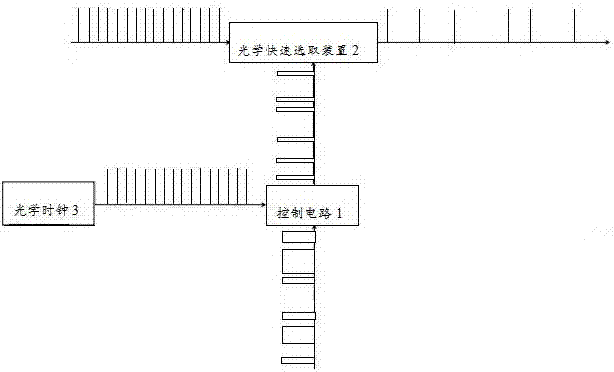
[0031] Such as figure 1 As shown, the embodiment of the present invention provides a high-energy picosecond laser pulse POD (pulse on demand) control system, including a control circuit 1, an optical fast selection device 2, and a main optical clock 3. The main optical clock 3 is connected to the Control circuit 1, the control circuit 1 is connected to the optical fast selection device 2, the main optical clock 3 is used as the basic clock of the control circu...


PUM


Abstract

The invention provides a high-energy picosecond laser pulse POD (Pulse on Demand) control system and a method. The system comprises a control circuit, an optical fast selection device, and a main optical clock. The main optical clock is connected with the control circuit. The control circuit is connected with the optical fast selection device. The main optical clock is used for emitting a base clock laser pulse signal and transmitting the base clock laser pulse signal to the control circuit. The control circuit is used for outputting a modulated pulse signal to the optical fast selection device according to the base clock laser pulse signal and a received external control pulse signal. The optical fast selection device is used for screening laser pulses emitted by a picosecond laser according to the modulated pulse signal. Every picosecond laser pulse required can be selected precisely from high-energy picosecond laser pulses as high as 1MHz. The POD function of the picosecond laser can be achieved. The laser output frequency can be modulated and changed in real time with external control signals.

Description

technical field [0001] The invention relates to the field of laser technology, in particular to a high-energy picosecond laser pulse POD control system and method. Background technique [0002] The picosecond laser with pulse energy of hundreds of μJ (microjoules) and repetition rate of hundreds of kHz (kilohertz) can meet the fine processing requirements of many materials and can be widely used in laser cutting and engraving , Scribing and marking and other fields. Picosecond laser processing technology has become a research hotspot in the field of laser processing, leading the trend of future laser processing. Since the user needs to quickly adjust the frequency of the laser pulse without changing the various parameters of the single pulse during the high-speed processing of materials using the picosecond laser, it is necessary to perform high-speed modulation output on the fixed-frequency optical pulse output by the laser. . The existing technology directly changes the...

Claims


Application Information

Patent Timeline
IPC IPC(8): H01S3/11
CPCH01S3/11
Inventor 吴艳清徐进林华仁忠易金豹
Owner WUHAN HUARAY PRECISION LASER
Learn More