Reactive compensation coordination control method during DC emergency power support process

A technology of power support and coordinated control, applied in reactive power compensation, reactive power adjustment/elimination/compensation, AC network circuits, etc. And other issues

Active Publication Date: 2017-08-18
NARI TECH CO LTD +3
View PDF8 Cites 20 Cited by
  • Summary
  • Abstract
  • Description
  • Claims
  • Application Information

AI Technical Summary

Problems solved by technology

[0007] The purpose of the present invention is: in view of the prior art, in the process of DC emergency power support, the AC voltage of the converter station is too low to maintain the DC current following the output current setting value of the DC power regulat

Method used


Image

  • Reactive compensation coordination control method during DC emergency power support process
  • Reactive compensation coordination control method during DC emergency power support process
  • Reactive compensation coordination control method during DC emergency power support process

Examples


Embodiment 1

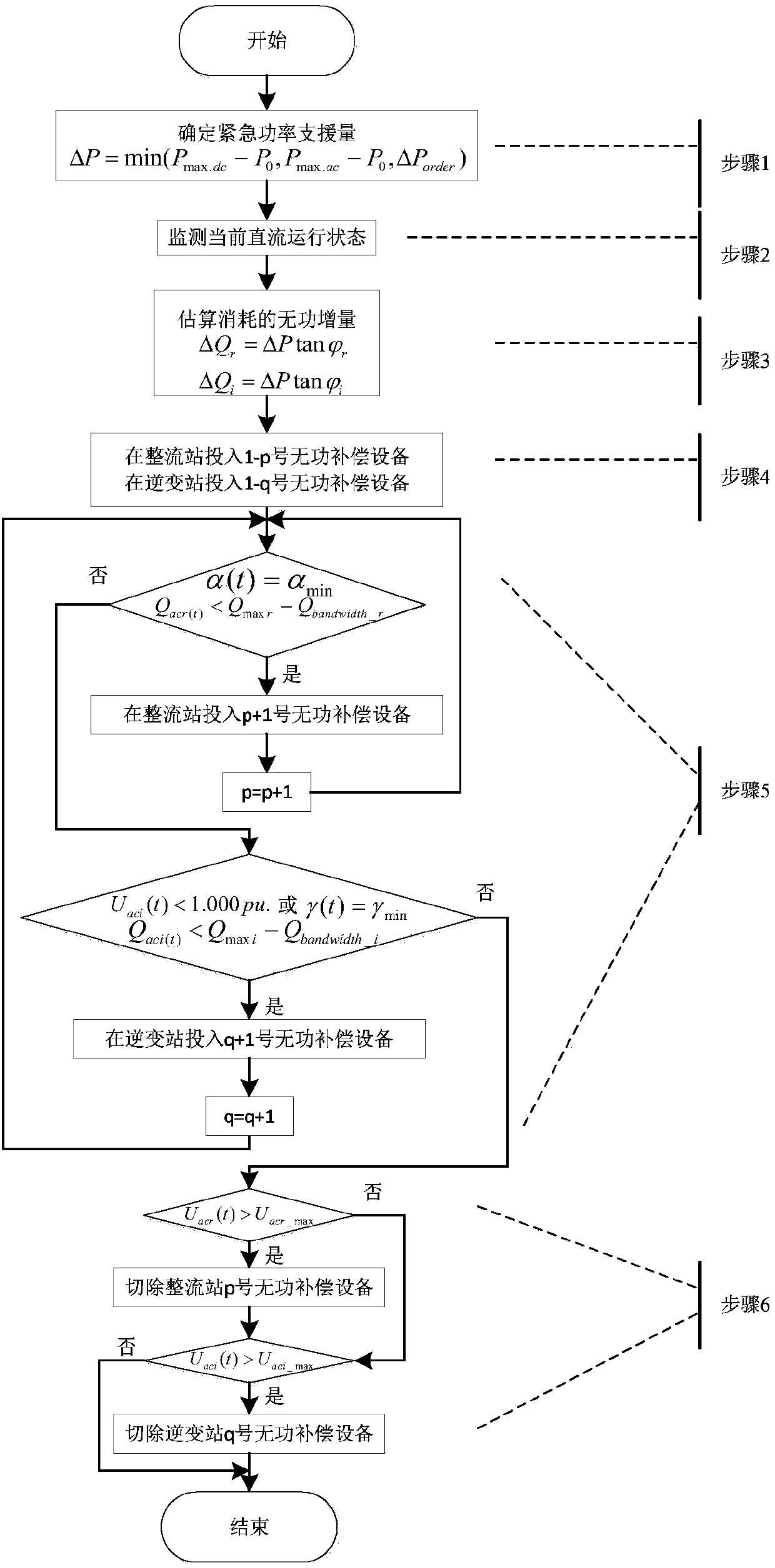
[0040] This embodiment is a kind of implementation mode of the present invention, and its process is as follows figure 1 shown.

[0041] figure 1 In step 1, the description is based on the short-term overload capacity P of the DC itself max.dc , The maximum DC transmittable power P under the current operation mode of the AC-DC system max.ac And the power ΔP that needs the DC emergency support under the current system failure corresponding to the emergency control strategy table order , to determine the actual emergency power support amount ΔP:

[0042] ΔP=min(P max.dc -P 0 ,P max.ac -P 0 ,ΔP order )

[0043] Among them, P 0 is the current DC active power.

[0044] figure 1 In step 2, it is described to monitor the commutation angle μ of the rectification side in the current DC operation mode r and the firing angle α and the inverter side commutation angle μ of the current DC operation mode i and turn-off angle γ.

[0045] figure 1 Step 3 in the above describes ...


PUM


Abstract

The present invention discloses a reactive compensation coordination control method during the DC emergency power support process and belongs to the technical field of power systems and automation. According to the technical scheme of the invention, according to a current running state and a to-be-lifted DC power, a reactive power, required to be consumed additionally for the DC system after the active power thereof is boosted, is estimated. Before the DC boosting process, filters or parallel capacitors of a corresponding number are put to use in the emergency manner. After the DC boosting process, reactive-load compensation equipment is put to use additionally according to the actual control manner of a convertor station. Meanwhile, the AC bus voltage of the convertor station is monitored. As a result, the condition that the AC voltage of the convertor station is out of limit due to the usage of the reactive-load compensation equipment can be avoided. The method can effectively improve the amount of the actual emergency power support in the DC large modulation mode. Meanwhile, the power imbalance problem of the power grid of a receiving end can be effectively relieved, and the safety and the stability of the power grid are improved.

Description

technical field [0001] The invention belongs to the technical field of electric power system and automation thereof. More precisely, the invention relates to a reactive power compensation coordination control method in the DC emergency power support process. Background technique [0002] At present, many regions in my country have formed a grid structure with multiple DC feeds. Due to the large capacity of ultra-high voltage and ultra-high voltage DC transmission, if a DC blocking fault occurs, it will simultaneously cause a large unbalanced power in the power grid at the sending and receiving end, and the impact The transient stability of the system. [0003] Compared with the emergency control measures of the AC system, the emergency power support (EDCPS) of the non-fault DC system is used to improve the transient stability of the AC system under high-power shock disturbance, the control cost is lower, and the control is faster and more reliable. For the overload capacity ...

Claims


Application Information

Patent Timeline
IPC IPC(8): H02J3/18H02J3/36
CPCH02J3/1821H02J3/36Y02E40/30Y02E60/60
Inventor 吴雪莲李兆伟刘福锁李威李碧君方勇杰黄慧王燕君张子龙谭真
Owner NARI TECH CO LTD
Why Eureka
Try Eureka