IGBT grid resistor variable circuit
A gate resistance and resistance technology, applied in the field of switching power supply, can solve problems such as unfavorable IGBT reliable shutdown, and achieve the effect of eliminating Miller effect
- Summary
- Abstract
- Description
- Claims
- Application Information
AI Technical Summary
Problems solved by technology
Method used
Image


Examples
Embodiment Construction
[0009] The present invention will be further described below in conjunction with specific examples.
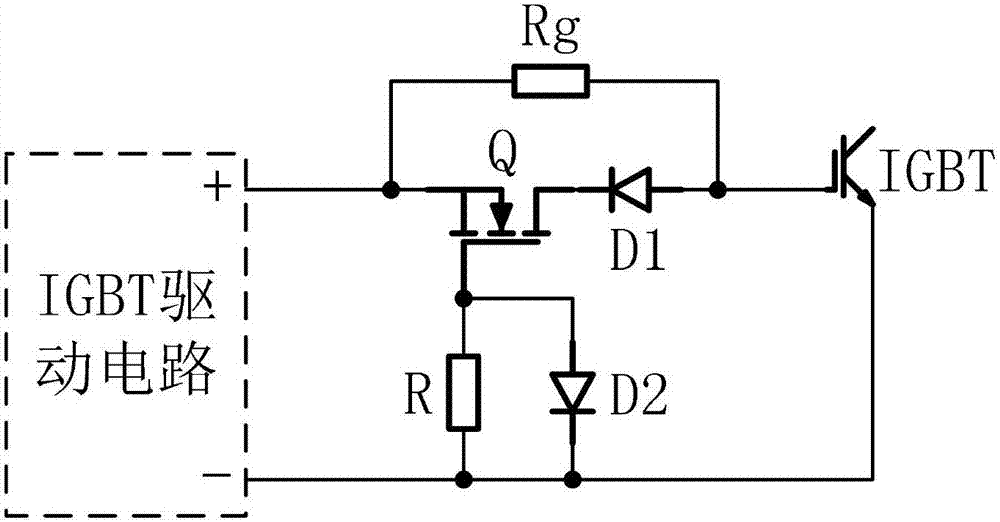
[0010] Such as figure 2 As shown, an IGBT gate resistance variable circuit according to an embodiment of the present invention includes an IGBT drive circuit, a first resistor Rg, a second resistor R, a first diode D1, a second diode D2, a field Effect tube Q and IGBT; the first resistor Rg is the IGBT gate resistor; the field effect tube Q is an N-channel enhancement type; the IGBT drive circuit outputs the drive voltage through the positive and negative terminals; the positive pole of the IGBT drive circuit and the first resistor Rg One end of the field effect transistor Q is connected to the source; the negative electrode of the IGBT drive circuit is connected to the emitter of the IGBT, one end of the second resistor R and the cathode of the second diode D2; the gate of the field effect transistor is connected to the second resistor The other end of R2 is connected to th...
PUM
 Abstract
Description
Claims
Application Information
 - R&D
- Intellectual Property
- Life Sciences
- Materials
- Tech Scout
- Unparalleled Data Quality
- Higher Quality Content
- 60% Fewer Hallucinations
Browse by: Latest US Patents, China's latest patents, Technical Efficacy Thesaurus, Application Domain, Technology Topic, Popular Technical Reports.
© 2025 PatSnap. All rights reserved.Legal|Privacy policy|Modern Slavery Act Transparency Statement|Sitemap|About US| Contact US: help@patsnap.com