
Estimation Method of Initial Rotor Position of Electrically Excited Synchronous Motor

A technology of rotor initial position and synchronous motor, applied in the direction of motor generator control, electronic commutation motor control, control generator, etc., can solve the problems of reduced system reliability, complex algorithm, and inability to guarantee the accuracy of estimation results, etc., to achieve The algorithm is simple and practical, there is no hardware signal interference problem, and the effect of expanding the scope of application

Active Publication Date: 2019-07-05
BEIJING LEADER & HARVEST ELECTRIC TECH
View PDF3 Cites 1 Cited by
  • Summary
  • Abstract
  • Description
  • Claims
  • Application Information

AI Technical Summary

Problems solved by technology

However, it can be found from actual implementation that the use of mechanical sensors such as resolvers and absolute photoelectric encoders increases the cable connection and interface circuit between the synchronous motor and the control system, and the sensor signal and control system are susceptible to interference, which will reduce the system performance. reliability
However, the algorithm of high-frequency injection or observer is too complicated and the result depends on the parameters of the synchronous motor or the accuracy of the algorithm itself, so the accuracy of the estimation result cannot be guaranteed

Method used


Image

  • Estimation Method of Initial Rotor Position of Electrically Excited Synchronous Motor
  • Estimation Method of Initial Rotor Position of Electrically Excited Synchronous Motor
  • Estimation Method of Initial Rotor Position of Electrically Excited Synchronous Motor

Examples


Embodiment Construction

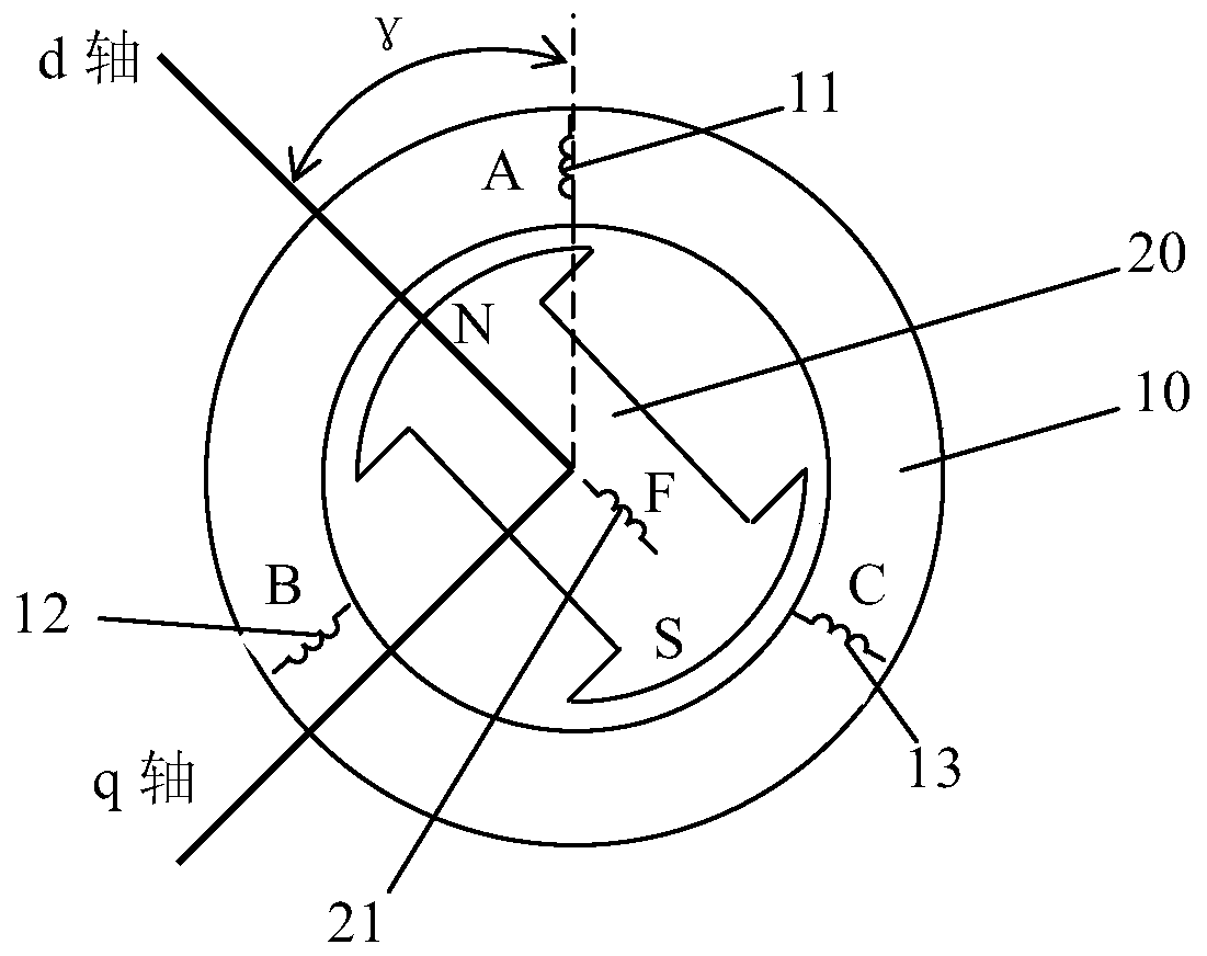
[0025] The estimation method of the present invention is designed for various types of electric excitation synchronous motors, figure 1 The structure diagram of a three-phase two-pole electric excitation synchronous motor is given as an example. Since the electric excitation synchronous motor is a well-known device in the field, it will not be described in detail here, but only briefly introduced. like figure 1 , the electric excitation synchronous motor includes a stator 10 and a rotor 20, and the stator winding includes an A-phase stator winding 11, a B-phase stator winding 12 and a C-phase stator winding 13, which are the same as the three-phase stator windings of an asynchronous motor, and the rotor 20 is provided with a through The rotor winding 21 (excitation winding) with DC current (excitation current) is input, and the DC current is passed into the rotor 20 through a static rectifier via a slip ring, a brush, or through a brushless excitation method. In addition, a ...


PUM


Abstract

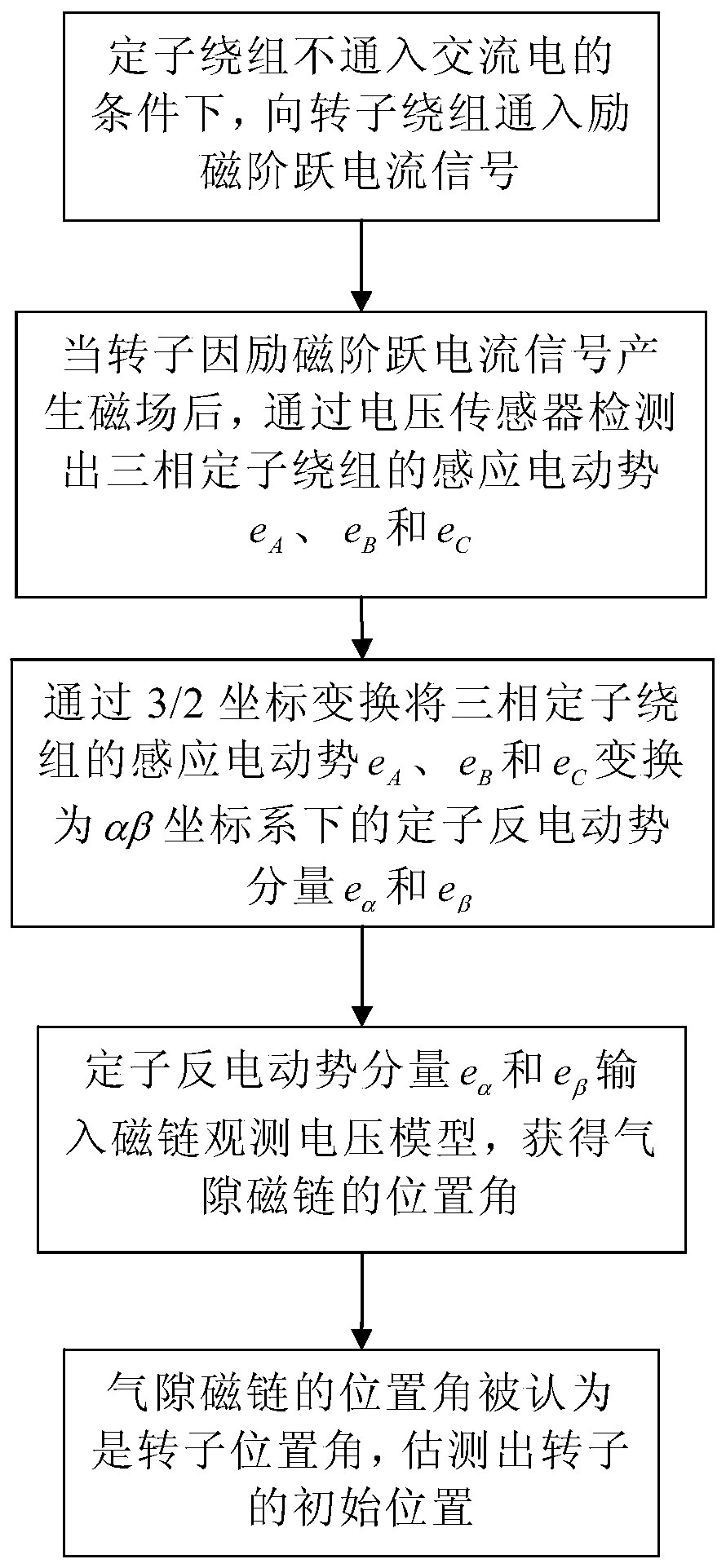
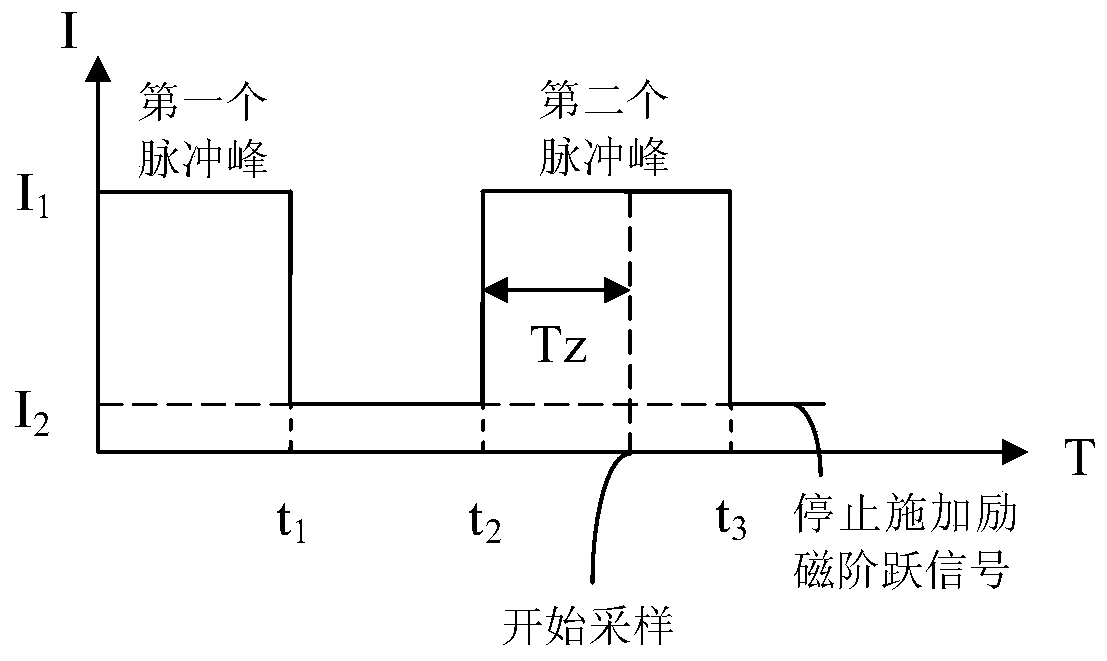
The invention discloses an excitation synchronous motor rotor initial position estimation method. The method includes the following steps that: under a condition that alternating current is not introduced into stator windings, excitation step current signals are introduced into a rotor winding; after an excitation synchronous motor generates a magnetic field due to the excitation step current signals, the induced electromotive forces of the three-phase stator windings are detected through a voltage sensor, and the induced electromotive forces of the three-phase stator windings are transformed into stator back-electromotive force components in an alpha-beta coordinate system through 3 / 2 coordinate transformation, and the stator back-electromotive force components are inputted into a voltage model, the position angle of air gap flux is obtained, and the position angle of the air gap flux is a rotor position angle, and therefore, the initial position of a rotor can be estimated. According to the method of the invention, the initial position of the rotor can be realized without a position sensor required, and therefore, the method is simple and practical, can accurately estimate the initial position of the rotor and is suitable for various kinds of electric excitation synchronous motors.

Description

technical field [0001] The invention relates to a method for estimating the initial position of a rotor of an electrically excited synchronous motor without using a position sensor, and belongs to the technical field of synchronous motors. Background technique [0002] Compared with asynchronous motors, in the case of large power or low speed, the frequency conversion speed regulation of electric excitation synchronous motors is technically and economically feasible, and the advantages are more obvious when the power increases. Moreover, the electric excitation synchronous motor also has its own advantages in terms of power factor, control accuracy, field weakening ratio, overload capacity, etc., and is suitable for high-power transmission occasions. Internationally, large-capacity air compressors, water pumps, mine hoists and rolling mills in industrial applications tend to be driven by electric excitation synchronous motors. In recent years, with the expansion of domestic...

Claims


Application Information

Patent Timeline
Patent Type & Authority Patents(China)
IPC IPC(8): H02P21/18H02P6/182
CPCH02P6/182
Inventor 贺艳晖
Owner BEIJING LEADER & HARVEST ELECTRIC TECH
Learn More