Energy storage system for vehicle

An energy storage system and vehicle technology, applied in the field of energy storage systems

Active Publication Date: 2017-08-18
VOLKSWAGEN CHINA INVESTMENT
View PDF6 Cites 2 Cited by
  • Summary
  • Abstract
  • Description
  • Claims
  • Application Information

AI Technical Summary

Problems solved by technology

However, when the engaged lower case flange and upper case flange are fastened together by screwing nuts onto bolts, the axial fastening force of the bolts acts

Method used


Image

  • Energy storage system for vehicle
  • Energy storage system for vehicle
  • Energy storage system for vehicle

Examples


Embodiment Construction

[0038] In the following preferred embodiments, a battery assembly is described as an example of an energy storage system.

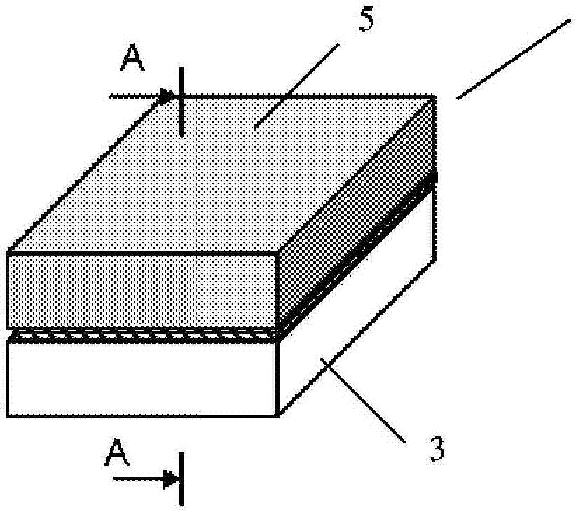
[0039] figure 1 is a schematic diagram of a battery assembly for a vehicle according to the present invention. Such as figure 1 As shown, a battery assembly 1 for a vehicle according to the present invention generally includes a lower case 3, an upper case 5, and a plurality of battery modules accommodated in an inner space formed by the lower case 3 and the upper case 5 (in figure 1 not visible in ). Although the lower housing 3 and the upper housing 5 are shown as being box-shaped, it should be understood that the lower housing 3 and the upper housing 5 may be of any shape desired. Although the lower case 3 and the upper case 5 may be made of plastic, it is preferable that the lower case 3 is made of a metal material to support the weight of the battery module. Of course, the upper casing 5 can also be made of metal material. Multiple battery modul...


PUM


Abstract

An energy storage system for vehicle comprising a lower housing (3) and an upper housing (5) connecting with each other; and a plurality of battery modules connected in an internal space defined by the lower housing (3) and the upper housing (5), and connected in serial or in parallel to supply power to a battery-power driven motor of the vehicle. It is possible to establish a good seal connection between the lower housing (3) and the upper housing (5) of the energy storage system.

Description

technical field [0001] The present invention relates to energy storage systems, and more particularly to battery assemblies for vehicles. Background technique [0002] In recent years, hybrid electric vehicles (HEVs) or electric vehicles (EVs) have been widely developed. They are equipped with a high-capacity energy storage system such as a battery pack and use an electric motor powered by battery power as the driving source for operation. A battery assembly generally includes a lower case, an upper case, and a plurality of battery modules accommodated in an inner space formed by the lower case and the upper case. Multiple battery modules are connected in series or in parallel to power a motor driven by battery power. The inner space formed by the lower case and the upper case must be a sealed space. In this way, on the one hand, it is possible to prevent liquids, such as water or cooling liquid, from entering the inner space so as to avoid any electric shock, leakage and...

Claims


Application Information

Patent Timeline
IPC IPC(8): H01M10/04H01M2/02H01M2/08H01M50/172H01M50/183H01M50/204H01M50/262H01M50/271
CPCH01M2220/20Y02E60/10H01M50/24Y02P70/50H01M50/204H01M50/262H01M50/271
Inventor U·拉赫蒙德
Owner VOLKSWAGEN CHINA INVESTMENT
Why Eureka
Try Eureka