
Micro-nozzle and manufacture method thereof

A manufacturing method and technology for micro-nozzles, which are applied in separation methods, chemical instruments and methods, spraying devices, etc., can solve the problems of high manufacturing cost of micro-channel devices, complex micro-channel device processes, and high process environment requirements, and are easy to learn and master. , The effect of low production cost and low process environment requirements

Inactive Publication Date: 2011-09-21
NANJING UNIV OF SCI & TECH
View PDF0 Cites 2 Cited by
  • Summary
  • Abstract
  • Description
  • Claims
  • Application Information

AI Technical Summary

Problems solved by technology

These equipment, especially the reactive ion etching equipment, are expensive, so the manufacturing cost of the micro-channel device is high; using this method to make the micro-channel device is complex and requires high requirements for the operator and the process environment

Method used


Image

  • Micro-nozzle and manufacture method thereof
  • Micro-nozzle and manufacture method thereof
  • Micro-nozzle and manufacture method thereof

Examples


Embodiment Construction

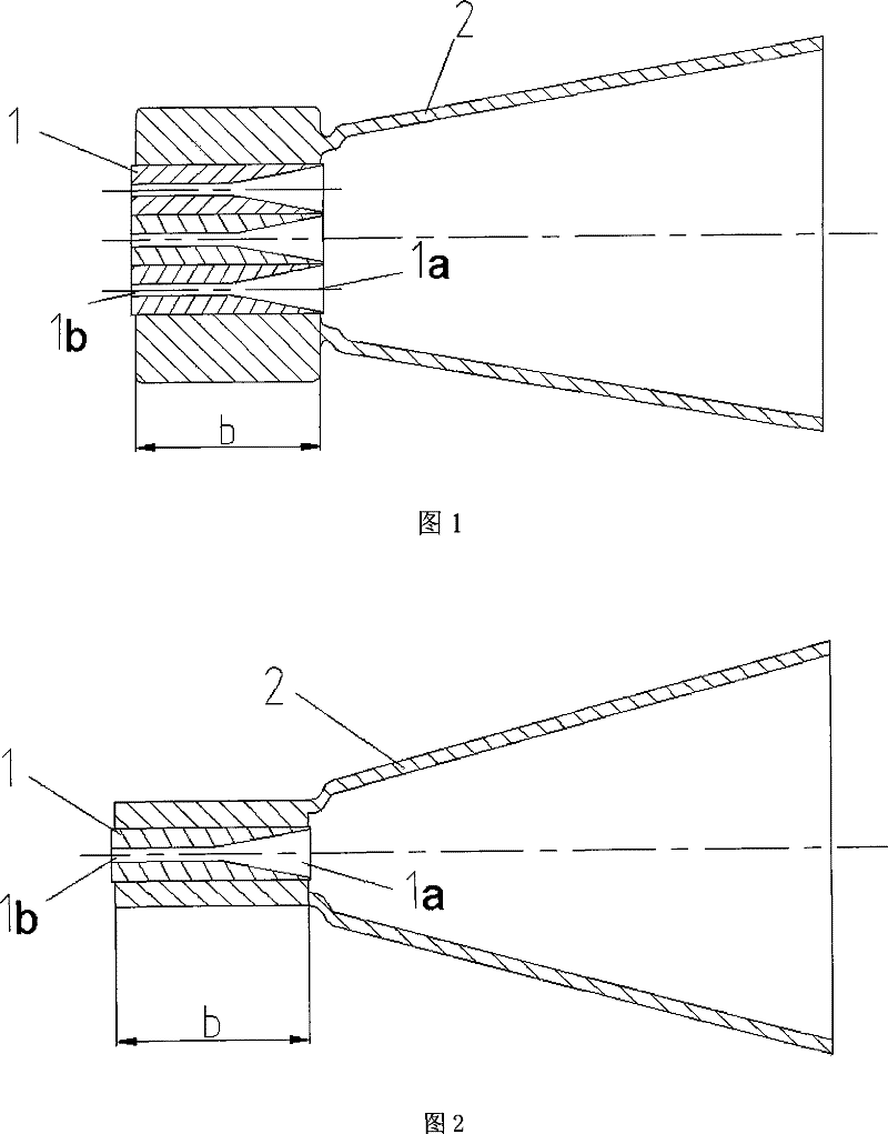
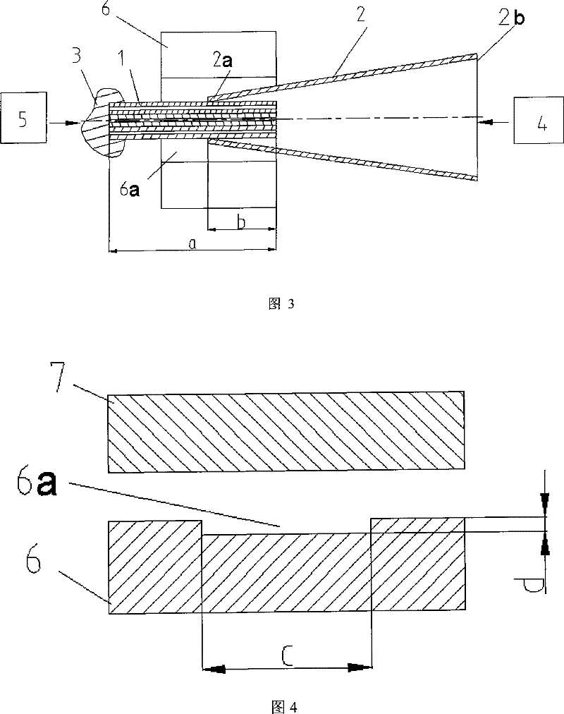
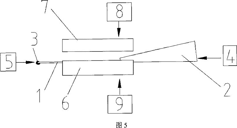
[0020] combine figure 1 And Fig. 2, the capillary 1 of micronozzle of the present invention is made up of micropipe 1b and transition duct 1a, and this capillary 1 is embedded in an end of plastic pipe 2, and this micropipe 1b communicates with nozzle external environment, and this transition duct 1a is connected with plastic pipe 2 The inner cavity of the transition duct 1a is communicated with each other, and the inner diameter of the transition duct 1a gradually decreases. Wherein, there is one or more than one capillary tube 1 , and the axes of the more than one capillary tube 1 with the same outer diameter are arranged in parallel in a row in the same plane. The plastic pipe 2 is a thermoplastic pipe, and the cross-sectional shape of the inner cavity perpendicular to the axis of the plastic pipe 2 is circular or gradually transitions from circular to oblate. The cross-sectional shape of the capillary lumen perpendicular to the axis of the capillary 1 is circular. The in...


PUM

PropertyMeasurementUnit
lengthaaaaaaaaaa

Abstract

The invention discloses a micro-nozzle and a fabrication method thereof. A capillary tube of the micro-nozzle consists of a micro-pipe and a transitional pipe, and is embedded into one end of a plastic pipe; the micro-pipe is communicated with the environment outside the nozzle; the transitional pipe is communicated with the inner cavity of the plastic pipe; and the inside diameter of the transitional pipe is reduced gradually. The fabrication method of the micro-nozzle does not need to adopt micro-electromechanical processing technology and has fewer operating steps,,and common mechanical technicians can operate technologies such as die casting and corrosion and the like; therefore, the method is simple and reliable, and are easy to learn and master by operators; the circular-section plastic pipe of the micro-nozzle forms a fluid inlet tank which delivers fluid to the micro-pipe, simultaneously, macro-connection is formed between the fluid-inlet system and the capillary pipe so as tofacilitate the sealed connection with the common circular-section macro-fluid inlet pipes. Without any bending angles, fluid channels in the micro-nozzle are communicated straightly, which is easy for sample introduction, cleaning and drying.

Description

technical field [0001] The invention belongs to a micro-nozzle of an injection device for preparing microcapsules and micro-emulsions and a manufacturing method thereof. Background technique [0002] At present, through-type microchannel devices used in the preparation of microcapsules and microemulsions are mostly fabricated by microelectromechanical processing methods, and the general fabrication steps include mask fabrication, glue coating, exposure, corrosion, and glue removal. Typical a kind of microemulsification microchannel and manufacture method thereof as described in detail such as Isao Kobayashi mainly include the following steps: a) deposit a layer of 0.2 μm thick aluminum layer on the silicon substrate by the method of vapor deposition as A protective layer for deep ion etching; b) coating a layer of photoresist on this substrate; c) transferring the micropipe shape layout on the mask to the photoresist by ultraviolet exposure; d) developing the aluminum film ...

Claims


Application Information

Patent Timeline
Patent Type & Authority Patents(China)
IPC IPC(8): B81B1/00B81C5/00B05B1/00B01J13/00
Inventor 侯丽雅张晓乐章维一
Owner NANJING UNIV OF SCI & TECH
Learn More