
Dynamo-electric machine

A technology for rotating electrical machines and rotors, applied in electrical components, electromechanical devices, electric components, etc., can solve problems such as heating of stators and stator coils, lower operating efficiency, etc., achieve pressure loss suppression, high efficiency, and small and lightweight Effect

Inactive Publication Date: 2017-08-18
MITSUBISHI ELECTRIC CORP
View PDF8 Cites 12 Cited by
  • Summary
  • Abstract
  • Description
  • Claims
  • Application Information

AI Technical Summary

Problems solved by technology

In the above-mentioned rotating electric machine, since current flows through the stator coil when the rotor rotates, the stator and the stator coil generate heat, and this heat reduces the operating efficiency

Method used


Image

  • Dynamo-electric machine
  • Dynamo-electric machine
  • Dynamo-electric machine

Examples


Embodiment Construction

[0023] Hereinafter, embodiments of the rotating electric machine according to the present invention will be described using the drawings.

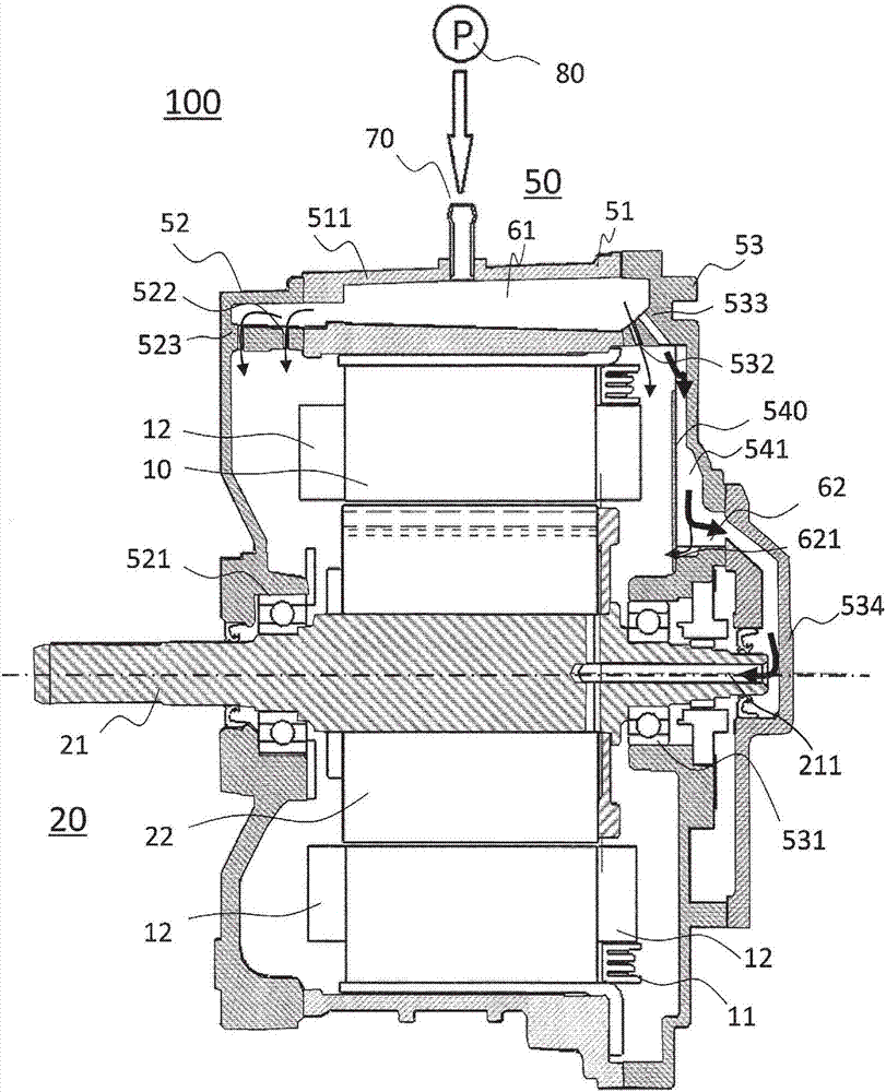
[0024] figure 1 It is a schematic cross-sectional view showing one embodiment of the rotating electric machine 100 of the present invention, that is, a cross-sectional view in the direction of the rotation axis of the rotating electric machine 100 .

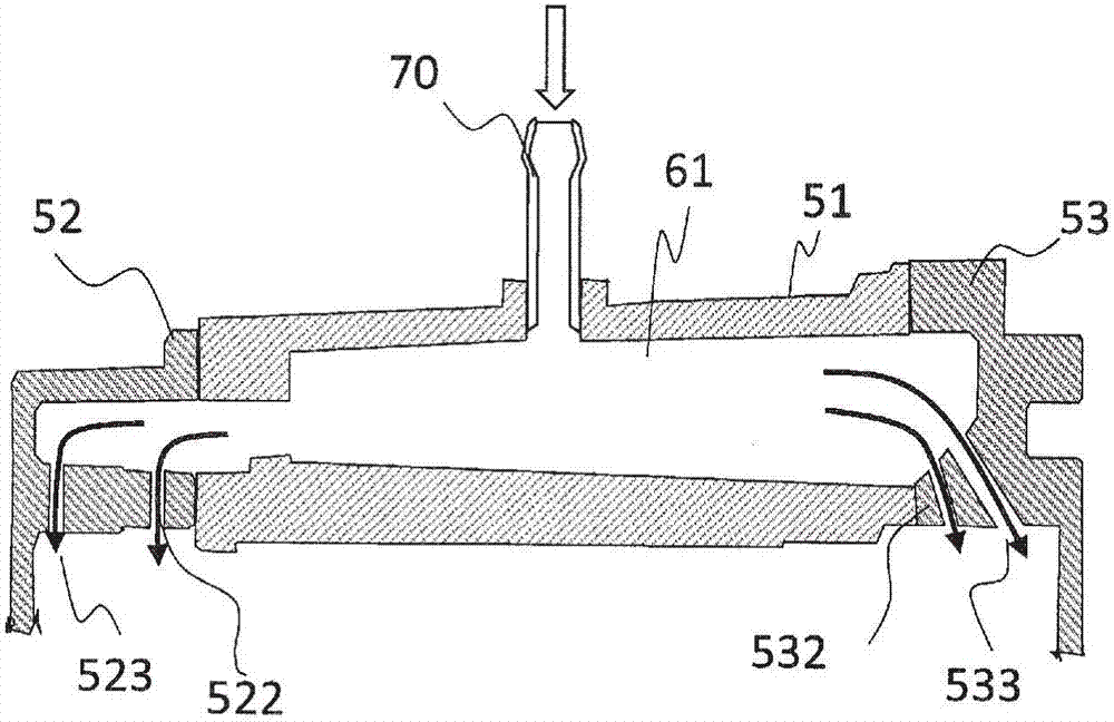
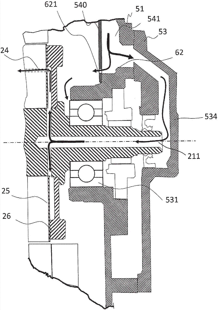
[0025] The casing 50 of the rotating electrical machine 100 includes a middle frame 51 of the main body, a front frame 52 and a rear frame 53, and forms a structure in which both ends of the above-mentioned middle frame 51 are closed by the front frame 52 and the rear frame 53, and the stator 10 is fixed in the middle of the above-mentioned casing 50 The frame 51 and the rotating shaft 21 of the rotor 20 are supported by the front frame 52 and the rear frame 53 via bearings 521 and 531, respectively. In addition, the stator 10 has a divided cylindrical shape arranged in an annular shape, and...


PUM


Abstract

In order to efficiently cool a stator and a rotor of a dynamo-electric machine, cooling oil is supplied in a pressurized state by a pump to a first reservoir provided in a top part within a housing, and after the cooling oil is sprayed from the first reservoir, the cooling oil is guided by gravity to a cooling structure for a coil end of the stator, and a cooling structure for a bearing and a rotor iron core of the rotor.

Description

technical field [0001] The present invention relates to a rotating electrical machine, and more particularly to a rotating electrical machine in which a stator and a rotor are cooled by cooling oil. Background technique [0002] A rotating electric machine is composed of a rotatable rotor and a stator provided to surround the rotor, and a rotating electric machine that obtains the rotational force of the rotor by passing electricity to the stator coil wound on the stator is an electric motor, and generates current in the stator coil by rotating the rotor A rotating electric machine is a generator. In the above-mentioned rotating electric machine, since a current flows through the stator coil when the rotor rotates, the stator and the stator coil generate heat, and this heat reduces the operating efficiency. Therefore, the rotor and the stator are cooled to maintain operating efficiency. [0003] As the above-mentioned cooling method, in order to supply the cooling oil to t...

Claims


Application Information

Patent Timeline
Patent Type & Authority Applications(China)
IPC IPC(8): H02K9/19
CPCH02K9/19H02K5/203
Inventor 橘田佳明尾岛宏一高木胜成井上正哉东野浩之
Owner MITSUBISHI ELECTRIC CORP
Learn More