
Sintering process denitration system for sintering flue gas circulation

A technology of sintering process and sintering flue gas, which is applied in the field of flue gas denitrification system in the field of environmental protection. It can solve the problems of not being fully popularized and applied, flue gas partitioning, quality separation cycle, energy saving and emission reduction effect, etc., reaching a broad market Application prospect, reduction of external discharge, and effect of saving power consumption

Active Publication Date: 2020-06-02
武汉钢铁有限公司
View PDF6 Cites 0 Cited by
  • Summary
  • Abstract
  • Description
  • Claims
  • Application Information

AI Technical Summary

Problems solved by technology

[0010] However, the flue gas cycle currently carried out has not been divided into different types of flue gas, and the effect of energy saving and emission reduction is not obvious, so that it has not been fully promoted and applied in China.

Method used


Image

  • Sintering process denitration system for sintering flue gas circulation
  • Sintering process denitration system for sintering flue gas circulation
  • Sintering process denitration system for sintering flue gas circulation

Examples


Embodiment Construction

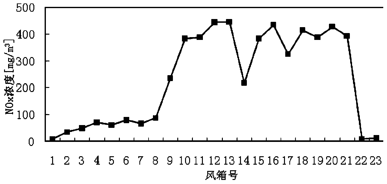
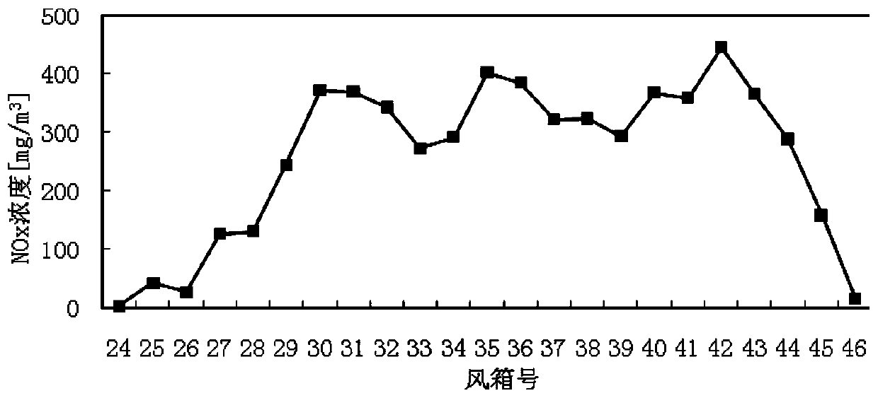
[0037] Referring to Fig. 1, the system of the present invention includes a sintering machine 2, a bellows 6 is provided under the trolley 2.1 of the sintering machine 2, and the outlet at the bottom of the bellows 6 is connected to the flue pipe, and the sintering machine is divided into ignition section, There are 4 areas including the head section, the flue gas rapid heating section, and the tail section. The air box 6 below the tail section to the flue gas rapid heating section area is equipped with a liquid ammonia nozzle 4; the flue gas pipeline includes the main smoke Road 7, circulating flue gas main flue 13 and machine nose ignition section flue 10, the outlet of bellows 6 below the tail section and flue gas rapid heating section is connected to main flue 7, and the outlet of main flue 7 passes through circulating smoke The tube side or shell side of the gas heat exchanger 11 is connected to the electrostatic / bag filter 14; the outlet of the bellows 6 below the head sec...


PUM


Abstract

The invention relates to a sintering process denitration system of sintering flue gas circulation. According to the technical scheme, the system includes a sintering machine, wherein an air bellow is arranged below a trolley of the sintering machine, and the bottom outlet of which is communicated with a flue gas pipeline; in the proceeding direction of the trolley, the sintering machine can be divided into four areas, successively including an ignition section, a machine nosing section, a flue gas rapidly-heating section and a machine tail section; the machine tail section and the air bellow positioned below the flue gas rapidly-heating section are both provided with a liquid ammonia nozzle respectively; the flue gas pipeline comprises a main flue gas pipeline and a main flue gas circulation pipeline, the machine tail section and an outlet of the air bellow positioned below the flue gas rapidly-heating section are both communicated with the main flue gas pipeline; an air bellow outlet of the machine nosing section is communicated with a flue gas circulation cover above the trolley of the sintering machine through the main flue gas circulation pipeline. The sintering process denitration system of sintering flue gas circulation has the advantages of being simple in system, great in controllability, friendly to environment, low in operational costs and capable of effectively getting rid of NOx in exhausted sintering flue gases, saving denitration investment, and achieving valid denitration without additionally purchasing catalysts.

Description

technical field [0001] The invention relates to a flue gas denitrification system in the field of environmental protection, in particular to a sintering process denitrification system with sintering flue gas circulation. Background technique [0002] In order to reduce the total amount of flue gas pollutants in the sintering process, sintering flue gas circulation has long been concerned by the industry as an important emission reduction scheme. For example, Xizheng Sato and others carried out research on the circulation of sintering flue gas as early as the 1980s, and recirculating part of the sintering flue gas into the sintering machine can significantly reduce the emission of exhaust gas, which can reduce emissions by 25-50%. Has significant environmental and social benefits. [0003] With the increasingly stringent environmental protection requirements, sintering flue gas circulation has once again become a current research hotspot. Fan Zhenyu and others studied the i...

Claims


Application Information

Patent Timeline
Patent Type & Authority Patents(China)
IPC IPC(8): B01D53/86B01D53/90B01D53/56
CPCB01D53/8631B01D53/90B01D2255/20738B01D2258/0283
Inventor 吴高明张垒卢丽君杨超
Owner 武汉钢铁有限公司
Learn More